Generation of sub-micron (nano) bubbles and characterization of their fundamental properties
Article information
Abstract
Although nanobubbles attract significant attention, their characteristics and applications have not been thoroughly defined. There are diverse opinions about the definition of nanobubbles and controversy regarding methods that verify their characteristics. This study defines nanobubbles as having a size less than 1 μm. The generation of these sub-micron (nano) bubbles may be verified by induced coalescence or light scattering. The size of a sub-micron (nano) bubbles may be measured by optical, and confocal laser scanning microscopy. Also, the size may be estimated by the relationship of bubble size with the dissolved oxygen concentration. However, further research is required to accurately define the average bubble size. The zeta potential of sub-micron (nano) bubbles decreases as pH increases, and this trend is consistent for micron bubbles. When the bubble size is reduced to about 700–900 nm, they become stationary in water and lose buoyancy. This characteristic means that measuring the concentration of sub-micron (nano) bubbles by volume may be possible by irradiating them with ultrasonic waves, causing them to merge into micron bubbles. As mass transfer is a function of surface area and rising velocity, this strongly indicates that the application of sub-micron (nano) bubbles may significantly increase mass transfer rates in advanced oxidation and aeration processes.
1. Introduction
The bubble size used for dissolved air flotation (DAF) usually ranges from 30 to 50 μm [1, 2]. This size results in an appropriate bubble collision efficiency and promotes the attachment of bubbles to particles in the water [3]. Also, this is an appropriate size for forming floating bubble-particle clusters. Recently, researchers have aimed to generate smaller bubbles for various applications [4, 5]. For example, Han [6] showed that for pressurized dissolution type bubble generators, that bubble size progressively reduces in size with an increased pressure. However, there is a critical bubble size below which it does not reduce in size any further. This critical size is about 30 μm, which occurs at a pressure of 3.5 bar and over.
Nanobubbles are a topical issue in industry. Various companies in Canada, Japan, South Korea, USA, and others have claimed to have generated nanobubbles by unique methods. These include pressurized dissolution, cavitation chambers, shear planes, ultra-fine pores, electrolysis, and swirling fluids in a mixing chamber. Also, now information about nanobubbles is widely available in the public domain [7, 8], many nanobubble-related organizations have subsequently emerged.
However, claims that various bubble generators produce nanobubbles are uncertain. There are neither certified international standards or standard methods for producing nanobubbles. Also, the size of nanobubbles has not yet been defined. Some organizations claim to use particle counters to suggest they have succeeded in measuring the size of a nanobubbles, however in most cases, it is not clear whether a bubble or a particle in the water has been targeted. Also, other measurement approaches used have not been scientifically proven to measure bubble size accurately.
Organizations claiming success in generating nanobubbles have also identified a variety application for their use. It has been claimed that: water treatment efficiency may be improved by the removal of algae, nitrogen, and phosphorous; growth rates may be accelerated in integrated fish and vegetable farms; enhanced cleaning of semi-conductors may be achieved, or the growth of cancer cells may be reduced. However, often these claims also lack evidence, or sufficient explanation of the theoretical principles or mechanisms used to achieve results for these applications.
As research regarding nanobubbles at an early stage of development, more theoretical and analytical frameworks are required to define the measurement, characteristics, and application of nanobubbles. Specifically, there are fragmented definitions of the term nanobubble. For example, International Standard Organization, Technical Standard for Nanotechnologies [9] defines a nanoparticle as a discrete piece of material with three external dimensions in the nanoscale length range between 1 and 100 nm. Moreover, International Standard [10] is currently discussing the definition of a bubble with a volume equivalent diameter of less than 100 μm and less than 1 μm as a fine bubble, and an ultra-fine bubble, respectively. In this study, a nanobubble is defined as having a diameter of less than 1 μm, which is also referred to in the more academically correct term of ‘sub-micron bubble’.
Thus, to resolve the lack of clarity regarding sub-micron (nano) bubbles generation and their applications, this study (1) identifies several methods of verifying the generation of sub-micron (nano) bubbles, and (2) verifies the fundamental characteristics of sub-micron (nano) bubbles. This lays the groundwork for sub-micron (nano) bubbles applications to identify which fields sub-micron (nano) bubbles can be applied to in a more scientifically rigorous way.
2. Verifying Sub-micron Bubbles Generation and Measuring the Bubble Size
In this study, a splitter type bubble generator was used to prove sub-micron bubbles generation has occurred. A splitter type bubble generator comprises a pump and a splitter chamber. Sub-micron bubbles are generated on the basis of the design parameters of the chamber and the operating conditions of the pump. This generator was devised to connect several mixing chambers in series, and it was confirmed that the bubble size decreases with the increase of the number of connected mixing chambers [5].
2.1. Verifying the Generation of Sub-micron Bubbles
2.1.1. The induced coalescence method
It was found that, when certain design parameters change, the size of generated bubbles gradually decreases. Bubble size was measured by particle counting method (PCM) (2400D, Chemtrac) [6, 11], and when 10 μm bubbles were generated, visibly milky colored water was produced as shown in Fig. 1(a). Irradiating ultrasonic waves were applied to this water, with a frequency of 28 Hz, and power of 60 W for 5 s, which caused coalescence where two or more bubbles merged to form single larger bubbles. Then, the single merged bubbles floated and disappeared at the surface. This process occurred so quickly that, when a second photo was taken the process was complete, as shown in Fig. 1(b).

Induced coalescence for verifying the presence of sub-micron bubbles generation: (a) micron bubbles (before), (b) micron bubbles (after), (c) sub-micron bubbles (before), (d) sub-micron bubbles (after).
Moreover, when bubbles with a size of 1 μm or less are generated, they are not able to be measured by PCM. As shown in Fig. 1(c) these generated bubbles are not visible in water. This is because the bubble size is so small, the scattering and backscattering efficiency of light is decreased [12]. When ultrasonic waves are irradiated using the same parameters as for micron bubbles (frequency of 28 Hz, power of 60 W, for 5 s), the water turns from clear to visibly milky, as shown in Fig. 1(d). The reasons for this are the existence of micron bubbles formed by coalescence. When irradiation continues, the bubbles became transparent like Fig. 1(b). Also, when distilled water was irradiated, with no bubbles, neither color change nor coalescence occurred. By this approach, the existence of sub-micron bubbles can be verified by induced coalescence. Besides ultrasonic waves, other external forces can also be used to verify the existence of sub-micron bubbles.
2.1.2. The light scattering method
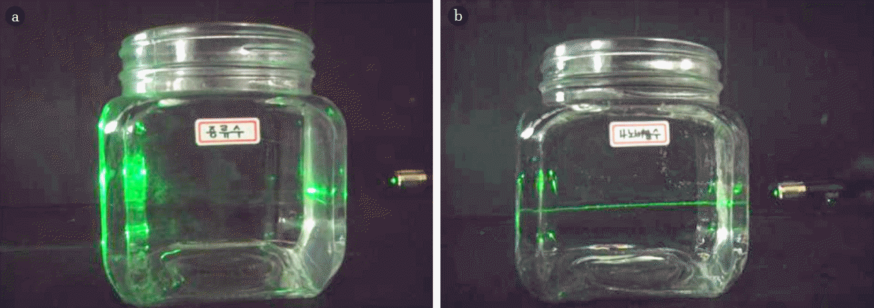
The existence of sub-micron bubbles may also be verified by light scattering. When a laser was directed at distilled water, as shown in Fig. 2(a), no visible line appeared because light scattering had not occurred. However, when the same laser was directed at water with generated sub-micron bubbles, such as in Fig. 1(c), a line reflecting the laser was visible, as shown in Fig. 2(b). By this approach, the existence of sub-micron bubbles can be verified.

Light scattering for verifying the presence of sub-micron bubbles generation: (a) distilled water with no bubbles, (b) sub-micron bubbles.
In this chapter, the existence of sub-micron bubbles could be verified by irradiating ultrasonic waves or laser. As an application of this method, we could ascertain the existence of sub-micron bubbles by simply noticing the occurred coalescence after putting sub-micron bubbles into a transparent container and causing a physical impact to the container. Also, dissolved oxygen (DO) concentration analysis tells us the presence of sub-micron bubbles. If surfactant or sodium chloride is included in the solution, the viscosity increases and causes the sub-micron bubbles to be generated comparatively easily. Therefore, the solution analysis beforehand is essential.
2.2. Measuring the Size of Sub-micron Bubbles
In this section, multiple methods are applied to measure the size of sub-micron bubbles.
2.2.1. Direct measurement – Optical image analysis
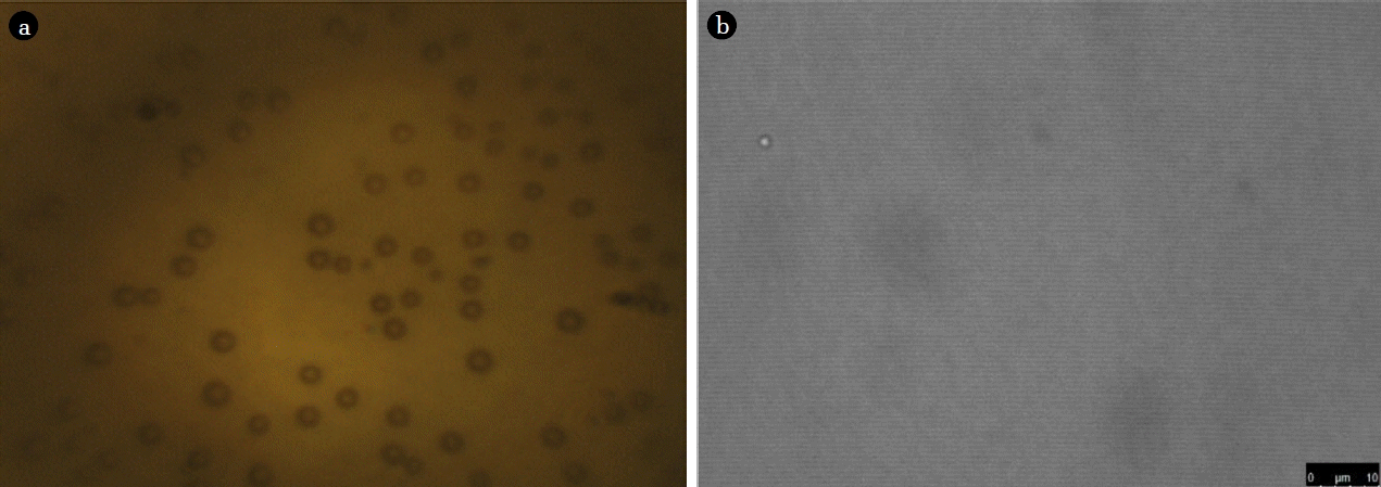
Fig. 3(a) shows an image of sub-micron bubbles in the water as shown in Fig. 1(c), taken by optical microscopy (Meiji Techno). In this image, the average bubble size measured is 854 nm. Optical microscopy can accurately measure the size of a single bubble. However, as bubble size becomes smaller, progressively more time is required to adjust the light intensity and focus on the individual bubbles. Hence, optical microscopy has advantages in verifying the existence of sub-micron bubbles but cannot provide exact values of the average bubble size for sub-micron bubbles because it cannot measure a large number of bubbles at the same time.

Optical image techniques for sub-micron bubble size measurement: (a) optical microscopy, (b) confocal laser scanning microscopy.
Fig. 3(b) shows a photo of a sub-micron bubbles taken by confocal laser scanning microscopy (CLSM) (SP8 X, Leica), with a 433 nm diameter. Since CLSM has increased resolution and contrast compared to optical microscopy, it can produce images of much smaller bubbles. However, as with optical microscopy, the method is not able to measure a large number of bubbles at a time, and it is difficult to determine an exact value for the average bubble size for sub-micron bubbles.
Besides these methods, several other approaches to measure the size of nanoparticles such as dynamic light scattering, laser diffraction methods, particle tracking analysis, and atomic force microscopy are used. These methods have the advantage of the capacity to measure large numbers of bubbles at the same time but still, require calibration. This presents a problem for light transmittance inside the bubbles, which limits the increased reliability of the measurements. More accurate calibration would be possible if the direct measurement method is employed when setting up calibration standards.
2.2.2. Indirect measurement – Dissolved oxygen (DO) reverse estimation
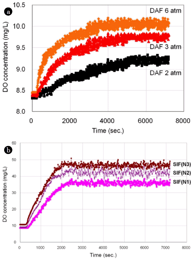
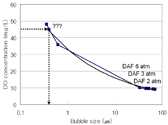
Fig. 4(a) shows the change in the dissolve oxygen concentration (ProODO, YSI) under three different pressures. For each pressure, the DO concentration was gradually increased until it reached a point where a steady-state DO value was maintained. The results of these experiments demonstrate two findings. The first is when the number of generated bubbles increases, through higher pressure or an increased recycle ratio, the time taken to reach the steady-state decreases. The second is that a negative correlation exists between bubble size and a steady-state DO concentration. To be specific, at pressures under 6 atm, the DO concentration is 10.1 ppm, and the average bubble size measured by PCM was found to be 33.4 μm. At pressures under 3 atm, the DO concentration is 9.7 ppm, and the average bubble size is 42.6 μm. At pressures under 2 atm, the DO concentration is 9.2 ppm, and the average bubble size is 71.3 μm. Using these results, the graph shape according to the DO concentration was estimated by the formula Eq. (1) as shown in Fig. 5. “a” was 20.67, “b” was 0.646, “c” was 7.89 when the variable coefficients were calculated on the basis of the DO concentration as shown in Fig. 5. At that time, RMSE was 0.011. This trend is consistent for sub-micron bubbles. As shown in Fig. 4(b), the DO concentration of sub-micron bubbles, generated by super-speed impeller flotation (SIF), shows a gradual increase until it reached a steady-state, which is the same trend shown in Fig. 4(a). For each condition N1, N2, and N3 changes were affected by manipulating the internal design parameters of the splitter chamber. From the empirical formula obtained, the estimated value of the average bubble size for each condition N1, N2, and N3 was estimated as 626 nm, 408 nm, and 359 nm, respectively. Although this method is simple to use for comparing sub-micron bubble sizes generated under different conditions, to more accurately estimate bubble size, the method DO reverse estimation method requires more data to be applied to the empirical model and further research. Or by applying a probability distribution function and cumulative distribution function, the accuracy can be increased with a relatively small amount of data [13].

DO concentration changes under various conditions: (a) under different pressure conditions, (b) under different design conditions.
3. Various Characteristics of Sub-micron Bubbles
3.1. Surface Area
If the bubble volume (V) is constant, the relationship between the surface area of the bubble (S) and average bubble size (r) can be expressed by Eq. (2), where surface area is inversely proportional to bubble size. So, if the bubble size becomes
3.2. Rise Velocity
Fig. 6(a) shows the rise velocity against bubble size for bubble sizes between 10 and 70 μm in diameter. Each point relates to a different bubble size measured by optical microscope, and the solid curve relates to theoretical modeling of this relationship using Stoke’s law. The results from the experimental measurements show a similar behavior to the theoretical prediction. As the bubble size decreases, the rise velocity also decreases. Within the micron bubble range, all bubbles regardless of size displayed buoyancy.

Rise velocity measurements: (a) micron bubbles, (b) sub-micron bubble (case 1), (c) sub-micron bubble (case 2).
However, for much smaller bubbles, unexpected behavior was observed. To measure the rise velocity of bubbles generated in Fig. 1(c), which have an average size of 854 nm, equipment consisted of a laser, a microscope and a video camera is used. When the laser is irradiated to bubbles, the laser is scattered. When it observed by microscope, it looks light twinkling at that position. Therefore, although the exact size is unknown, the location is traceable. And this equipment records the route of travel and travel time of them by video camera during that time. Fig. 6(b) and (c) show two sets of sequential images tracking two different sub-micron bubbles. The left-hand image was collected before movement, while the right-hand image was collected after movement. Each image was taken from the same perspective, across a 7-min intervals. Whereas the Stoke’s law model predicted that for a rise velocity of 854 nm, the rise velocity if the bubble would be 0.40 μm/s, the experimental measurements showed 0.78 μm/s for Fig. 6(b) and – 0.64 μm/s for Fig. 6(c). After tracking the movement of the sub-micron bubbles for more than 5 h, it was found that most were close to stationary in the water and moved slightly both in a vertical and horizontal direction. In this regard, it is assumed that, after bubble size reaches a certain point, the movement of the bubble is affected more by Brownian motion or density than buoyancy. These results show that bubble size is very important factor in mass transfer efficiency. Mass transfer rate is a function of surface area and rise velocity. So, if very small bubble is used which can hardly rise such as a sub-micron bubble, the mass transfer rate would increase exponentially. For ozone oxidation process which normally requires DOF facility, the necessity of DOF facility would be much lesser if sub-micron bubbles is applied because ozone gas is not rising when using sub-micron bubbles.
3.3. Zeta Potential
In DAF processes, coagulants are used to adjust the zeta potentials of bubbles and particles so that they can better attach to each other. Fig. 7(a) depicts several research outcomes showing the relationship between zeta potential variation and pH for 30 μm bubbles, which are commonly used for DAF processes [14–17]. Fig. 7(b) depicts the zeta potential variation with pH variation for 854 nm bubbles (Zeta phoremeter II, SEPHY). Both micron bubbles and sub-micron bubbles showed the same tendency. First, zeta potential of micron and sub-micron bubble is mostly negative in wide pH range. It is well known that the gas bubbles in aqueous media always have negative charges on their surfaces, which attribute to that the cations are more likely hydrated and thereby tend to stay in the bulk aqueous medium while the smaller less hydrated and more polarized anions trend to adsorb on the bubble surface [18]. And, as pH increases, the zeta potential decreases since the adsorption of OH− onto the gas-liquid interface leads to development of strong negative zeta potential [19]. Although it is difficult to compare exact values, as they were measured by different researchers, using different methodologies, all results showed the same tendency. Therefore, it is assumed that the zeta potential of both micron and sub-micron bubbles after adding coagulant have the same tendency.
3.4. Bubble Volume Concentration
The number of generated bubbles, which is referred to as the bubble volume concentration (BVC), is one of the most important factors for determining the efficiency of a bubble generator. For micron bubbles, the BVC is measured by the water substitution method as shown in Fig. 8(a). The BVC is obtained by measuring the water level difference before and after bubbles enter and leave the system boundary.

Schematic diagram of BVC measurement method (batch type): (a) micron bubbles, (b) sub-micron bubbles.
However, for sub-micron bubbles, it is difficult to measure the BVC because they exhibit stationary behavior and do not have buoyancy. To address this problem, as shown in Fig. 8(b), ultrasonic waves are irradiated between the two water-level-measuring process to cause coalescence and merge sub-micron bubbles into micron bubbles so that they rise. By measuring the water level after irradiation and comparing it with the initial water level, the BVC of sub-micron bubbles can be obtained. Additionally, to obtain more accurate results, it was necessary to use a narrow pipe to reduce the extent of capillary action, and generate as many bubbles as possible because the number of generated sub-micron bubbles is less than micron bubbles and to prevent the sub-micron bubbles from adhering to the pipe wall. The actual bubble volume measured in nano-bubbles was around 0.0001 mL/mL which is very small. Normally, the bubble volume is around 0.09 mL/mL in DAF which uses micron bubbles [20]. The difference in bubble volume between the two bubbles was about 100 times. We think this is because most of the energy generated by the pump was used to make shear force for splitting bubbles, which led to the decrease in the amount of generated bubble volume. Another possible reason is that, unlike micron bubble generator, sub-micron bubble generator used in this study did not have a compressor.
4. Conclusions
The generation of sub-micron (nano) bubbles can be verified by several methods. The size of sub-micron bubbles can also be measured using existing techniques, devices, and indirect measurement methods. However, to obtain more accurate average bubble size data, more research is required.
The surface area of sub-micron (nano) bubbles is inversely proportional to the decrease in their size. When the size of the bubbles is reduced to around 700–900 nm, they are close to being stationary in water and move slightly, both vertically and horizontally. As mass transfer from the bubbles is a function of the surface area and rise velocity, there is a strong probability that the application of sub-micron (nano) bubbles can significantly increase mass transfer rates in the advanced oxidation and aeration processes at water treatment plants and in oxygen supplies for fish farms. The zeta potential decreases as pH increases, and this trend is consistent for micron bubbles. As sub-micron bubbles are not buoyant, measuring their concentration by volume is possible by irradiating them with ultrasonic waves so that they merge into micron bubbles.
Given the nascent stage of research on sub-micron bubbles, there is a lack of theoretical and analytical frameworks for this phenomenon. Incremental research will not only increase the practical application of sub-micron bubbles in the environmental, medical, and agricultural fields, but will also open up new avenues for their use.
Acknowledgments
This research was supported by Korea Environment Industry & Technology Institute (KEITI) through Public Technology Program based on Environmental Policy, funded by Korea Ministry of Environment (MOE) (2018000200001).


