Effects of the carbon nanotube and polymer amounts on ultrafiltration membranes
Article information

Abstract
Composite membranes with nano-sized inorganic materials have high selectivity, high hydrophilicity, and improved fouling resistance. Blending Carbon Nanotubes (CNTs) in the polymer solution improves membrane properties like hydrophilicity, water permeability, selectivity, and fouling resistance. The effect of the polymer amount, together with the CNT amount in the polymer solution on membrane properties, was investigated in this work. There was more than 10% increase in the hydrophilicity of the membranes with 1% CNT addition, but it was not altered with the polymer amount. The porosity was increased almost 30% by 1% CNT addition in membranes prepared by 10% and 12% polymer concentration (P-10:C-0 and P-12:C-0), but only 16% increase in porosity occurred in membrane prepared by 15% polymer concentration (P-15:C-0). The flux of the P-15:C-0 membrane was increased four times by 1% CNT addition. Besides, fouling resistance of the membranes decreased with increasing polymer amount but increased with increasing CNT amount. BSA rejection increased with increasing polymer amount or CNT amount in the polymer solution. Hence membranes prepared with a higher amount of polymer are more prone to membrane property improvements with CNT addition. The increase in flux and selectivity by CNT addition in all membranes prepared with different polymer concentrations will increase the membrane life-time and reduce the treatment cost.
1. Introduction
Ultrafiltration can be considered as a porous membrane. The pore size of the ultrafiltration membranes typically ranges from 0.001 μm to 0.1 μm [1]. The structure of the ultrafiltration membranes is generally anisotropic, with a dense layer above the microporous layer. Separation is performed on the dense layer, and mechanical strength is provided by the microporous layer [2]. Although small suspended particles and dissolved macromolecules pass through the ultrafiltration membrane, bigger molecules are mainly rejected [3].
While polymeric membranes are flexible, tough, cheap, and have good separation properties, their mechanical, thermal, and chemical resistance are low. Besides, their fouling resistance is low due to their hydrophobic nature. Therefore, hybrid membranes made of organic and inorganic constituents draw attention. These membranes are expected to have a membrane forming property of the organic constituent and the physicochemical properties of the inorganic constituent [4]. Composite membranes with inorganic nanomaterials are noted for their improved properties, such as enhanced fouling resistance, selectivity, and hydrophilicity [5, 6].
Carbon nanotubes (CNTs) developed by Iijima in 1991 [7], have exceptional properties such as high aspect ratio, high mechanical and chemical stability, and high electrical conductivity [8]. The electrical, physical, chemical, and structural properties of CNTs have made them attractive candidates for new technologies for overcoming water scarcity and water pollution issues. CNT-based nanomaterials have been used as sorbents, catalysts, etc., in water treatment [9–12]. Pure CNTs are held together as clusters in polymer solution during membrane fabrication and considerably reduce permeability and the selectivity of the fabricated membranes. In addition, CNTs are hydrophobic and insoluble in most solvents. Because of these properties of the pure CNTs, functionalization is carried out. Positive (−NH3+), negative (−COO), or hydrophobic (aromatic rings) groups can be added to CNT surfaces with functionalization [13, 14]. CNT blended polymeric membranes exhibit high permeability, high thermal stability, improved mechanical strength, and high fouling resistance [15].
Choi et al. [16] and Qiu et al. [17] showed that morphology and the permeation properties of the composite membranes depend on the CNT amount by preparing polysulfone (PSU)/CNT composite membranes. Nechifor et al. [18] showed the successful removal of lead and mercury by PSU/CNT composite membranes. Celik et al. [19, 20] synthesized polyethersulfone (PES)/CNT composite membranes, which showed improved protein adsorption and higher fouling resistance. Zhao et al. [21] and Kim et al. [22] demonstrated the improved salt rejection performance and fouling resistance of the polyamide/CNT composite membranes. Wang et al. [23] prepared PES/CNT composite membranes for nanofiltration, which showed higher flux and salt rejection. Yang et al. [24] and Celik Madenli et al. [25] proved the improved antibacterial efficiency and suppressed biofilm growth of the PES/CNT composite membranes.
To date, several authors have shown the enhanced membrane properties like hydrophilicity, permeability, selectivity, and fouling and biofouling resistance by blending CNTs [16–29]. However, there have been no reports on the comparison of the membranes prepared in different polymer and CNT concentrations. This work aims to examine the effect of the polymer amount together with the CNT amount in the polymer solution on membrane properties. Membranes were prepared with different polymer and CNT concentrations to determine the effects of polymer and CNT amount in the polymer solution. To subsequently characterize the CNTs and fabricated membranes, water contact angle, pure water flux, permeation tests, Fourier transform infrared (FTIR) spectroscopy, and transmission electron microscopy (TEM) were used.
2. Materials and Methods
2.1. CNT Functionalization and Characterization
CNTs were functionalized in an acid mixture, as described elsewhere [27]. In brief, CNTs (Nanostructured and Amorphous Materials Inc., USA) were ultrasonicated at 70°C for 9 h in 3:1 (v/v) HNO3 (70%; Sigma-Aldrich, USA):H2SO4 (95–98%; Sigma-Aldrich, USA) mixture. After the acid treatment, CNTs were washed until a neutral pH and dried at 100°C overnight. The interaction mechanism is shown in Fig. 1.

Schematic representation of CNT functionalization and membrane fabrication.
The surface functional groups of nanotubes were detected by FTIR (Spectrum Two, PerkinElmer, USA), comprising a LiTaO3 MIR detector with a germanium crystal plate. Infrared spectra were recorded in the frequency range of 4,000–400 cm−1 with the resolution of 0.5 cm−1. The morphology of the raw and functionalized CNTs were analyzed by TEM (G2 F20; FEI Tecnai, USA). TEM samples were prepared by dropping suspension of CNTs in isopropyl alcohol on the copper grid with carbon film.
2.2. Membrane Fabrication and Characterization
Membranes were fabricated as described in our previous publications [19, 20]. In short, membrane solutions were prepared by ultrasonicating functionalized CNTs in 1:9 (v/v) n-methyl-2-pyrrolidinone (NMP, anhydrous 99.5%; Sigma-Aldrich, USA):N,N-Dimethylformamide (DMF, anhydrous 99.5%; Sigma-Aldrich, USA) mixture and dissolving PES (Veradel 3000P; Solvay Specialty Polymers, Germany). The prepared membrane solution was ultrasonicated and then cast by using a casting knife and a film applicator (1133N, Sheen, USA). Cast membrane solution was directly immersed into a coagulation bath. The schematic fabrication process of the membranes is presented in Fig. 1. Note that the membranes marked as P-10:C-0.5 refer to membranes prepared in a polymer solution in which the amount of PES was 10%, and the amount of CNTs with respect to PES was 0.5% by weight.
The contact angle goniometer (T200, KSV, USA) was used to measure the contact angles. The reported water contact angles were the average of at least seven measurements for each membrane. A one-way ANOVA test was applied (p < 0.05) to the results of contact angle measurements. The overall porosity (ɛ) of the membranes was calculated by using Eq. (1) [30, 31]:
where h is the membrane thickness (cm), A is the effective membrane area (cm2), ρw is the water density (0.9978 g/cm3 at 22°C), and Ww and Wd are the weight of the wet and dry membranes (g), respectively. The porosity data are the average value of at least two measurements for each membrane. The mean pore diameters of membranes (rm, μm) were determined by filtration velocity method according to Eq. (2) (Guerout–Elford–Ferry equation) [30, 32]:
where μ is water viscosity (9.544 × 10⁻⁴ Pa-s at 22°C), Q is the flowrate (cm3/s), and ΔP is the trans-membrane pressure (Pa).
2.3. Membrane Permeability and Selectivity
A dead-end membrane test unit (HP4750, Sterlitech, USA) with 14.66 cm2 of effective membrane area was used during the permeability and selectivity tests. The pressure source of the test unit was compressed air. 0.5 bar of constant transmembrane pressure was applied during permeability and selectivity tests. The water flux (Jw) and hydraulic resistance of the membranes (Rvm, m−1) were determined by using Eq. (3).
where V is the volume of the permeate (L), and Δt is time (h).
Bovine serum albumin (BSA, 1 g/L) filtration for 1 h was performed to examine the selectivity and fouling resistance. The protein flux (Jp) after 1 h of BSA filtration and BSA rejection ratio (R, %) was determined by using Eq. (4) and Eq. (5), respectively.
where Rfm (m−1) is the fouled membrane’s hydraulic resistance, and Cp (mg/L) and Cf (mg/L) are the BSA concentration of the permeate and feed solutions, respectively [28]. The molecular weight of BSA is approximately 68 kDa, and the molecular size is 14 nm×4 nm×4 nm [33].
3. Results and Discussion
3.1. CNT Functionalization and Characterization
CNTs aggregate because of strong van der Waals interactions to each other [34]. Besides, CNTs are chemically inert and insoluble in water or organic solvents [35]. The exceptional properties of the CNTs can be combined with other components by enhancing their solubility and processability through functionalization. CNTs can be functionalized by nitric acid, sulfuric acid, or mixtures of both. Functionalization introduces defects on the nanotube surface, cuts and shortens the CNTs, and opens the tips of the CNTs. The functionalization of CNTs introduces oxygen-containing groups at the tips and defect sites [36].
Fig. 2 shows the TEM images of the CNTs. While raw CNTs were 0.2–30 μm, functionalized CNTs were 50–500 nm. In addition, most of the raw CNTs had closed tips, yet functionalization opened their tips.

TEM images of raw CNT (a) and functionalized CNT (b)
FTIR spectra of the CNTs are given in Fig. 3. Even though there are three main peaks (~3,440 cm−1, ~1,630 cm−1, and ~1,560 cm−1) on raw CNTs (Fig. 3(a)), there are very clear five peaks (~3,440 cm−1, ~1,710 cm−1, ~1,630 cm−1, ~1,560 cm−1, and ~1,180 cm−1) on functionalized CNTs (Fig. 3(b)). The common peaks on both raw and functionalized CNTs that are ~ 3,440 cm−1, ~1,630 cm−1, and ~1,560 cm−1 correspond to adsorbed water [37–40], hydroxyl groups [39, 40] and carbon skeleton [40, 41], respectively. The new peaks appeared on functionalized CNTs, which are ~1,710 cm−1 and ~1,180 cm−1 correspond to CNT-COOH [37–40].

FTIR spectra of the raw CNT (a) and functionalized CNT (b).
To date, several authors demonstrate the functionalization of CNTs in a strong acid mixture. For instance, Choi et al. [16], Vatanpour et al. [42], and Norouzi et al. [43] functionalized CNTs in HNO3/H2SO4 = 1/3. They observed 1,430 cm−1, 1,520 cm−1, 1,680 cm−1, 1,715 cm−1, 2,857–2,970 cm−1, 3,435 cm−1 peaks that correspond to COOH, C-C, C-O, C=O, C-H, and −OH functional groups, respectively with FTIR analysis of functionalized CNTs. Celik et al. [19, 20], and Celik Madenli and Cakmakci [27] functionalized CNTs in HNO3/H2SO4 = 3/1. Celik et al. [20] showed that the length of the CNTs were 1~3.5 μm before acid treatment and 50–800 nm after acid treatment, and Celik Madenli and Cakmakci [27] showed that the length of the CNTs were ~10 μm before acid treatment and 500 nm after acid treatment. Moreover, in their studies, they observed peaks on functionalized CNTs at 3,440 cm−1, 1,630 cm−1, 1,460 cm−1, and 1,380 cm−1 correspond to −OH, C=O, O-C=O and −COOH, respectively with FTIR analysis of functionalized CNTs. As a result, the lengths of the CNTs are tens of micrometers before H2SO4:HNO3 treatment but shortened to hundreds of nanometers after H2SO4:HNO3 treatment. In addition, carboxylic groups were observed after the H2SO4:HNO3 treatment. Consistent with the previous research, TEM and FTIR results show that through a strong acid mixture treatment, CNTs were broken into smaller CNTs, tips were open, and carboxylic groups at the tips and the defect sites of the CNTs. These results verify the successful functionalization of the CNTs.
3.2. Membrane Characterization
Membrane performance strongly depends on surface chemistry [44]. Macromolecules tend to accumulate on the surface of the membranes because of the hydrophobic regions [45]. Membrane fouling can be reduced by increasing membrane hydrophilicity [46]. Membrane hydrophilicity can be investigated by measuring contact angles of membranes. The contact angle data of the fabricated membranes are displayed in Fig. 4. The membrane hydrophilicity improved with increasing CNT amount in polymer solution for all membranes because of the presence of functionalized CNTs containing carboxylic groups. However, changing the PES amount in the polymer solution did not induce statistically significant differences in the contact angles of fabricated membranes (by ANOVA tests). Hence, membrane hydrophilicity raised with increasing CNT amount, but it was not dependent on the PES amount.

Contact angles of the fabricated membranes.
The effect of polymer and CNT amounts on the porosity and mean pore diameter of the membranes are given in Table 1. While the porosity decreased with increasing PES amount in the polymer solution, it increased with increasing the CNT amount in the polymer solution. Higher polymer concentration results in a lower porosity [1]. Pore sizes of the fabricated membranes reduced with increasing the CNT amount or PES amount in the polymer solution. In other words, the porosity is directly proportional to the CNT amount in the polymer solution, while the pore size is inversely proportional. This result can be explained by the delayed phase separation because of the enhanced casting solution viscosity by increasing polymer and CNT amount [19, 47].
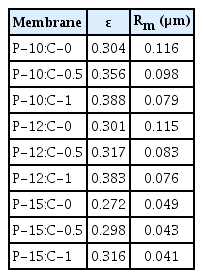
Porosity and Mean Pore Size of the Membranes
3.3. Membrane Permeability and Selectivity
A decrease in flux is observed in polymeric membranes due to the compression of the pores with applied pressure, which is called membrane compaction. It is very common in pressure-driven membrane processes. When the membrane is compacted, steady-state performance is achieved [48]. As shown in Fig. 5, membrane compaction was achieved in 2 h of water filtration for all membranes. The permeability of the PES membranes is high because of its polarity and hydrophilicity [49]. Pure water flux decreased with increasing PES amount, which is consistent with the pore diameters of the membranes. The smaller pores resulted in reduced pure water flux. Higher polymer concentration results in lower porosity and flux [1]. Consistent with the membrane pore size, the pure water flux decreased with a 0.5% CNT addition in the polymer solution. Even though the pore size reduced with 1% CNT addition, the pure water flux increased, probably because of the enhanced hydrophilicity and porosity of the membranes by CNT addition. Membrane flux strongly depends on the overall porosity and the top surface properties of a membrane [16, 50, 51].
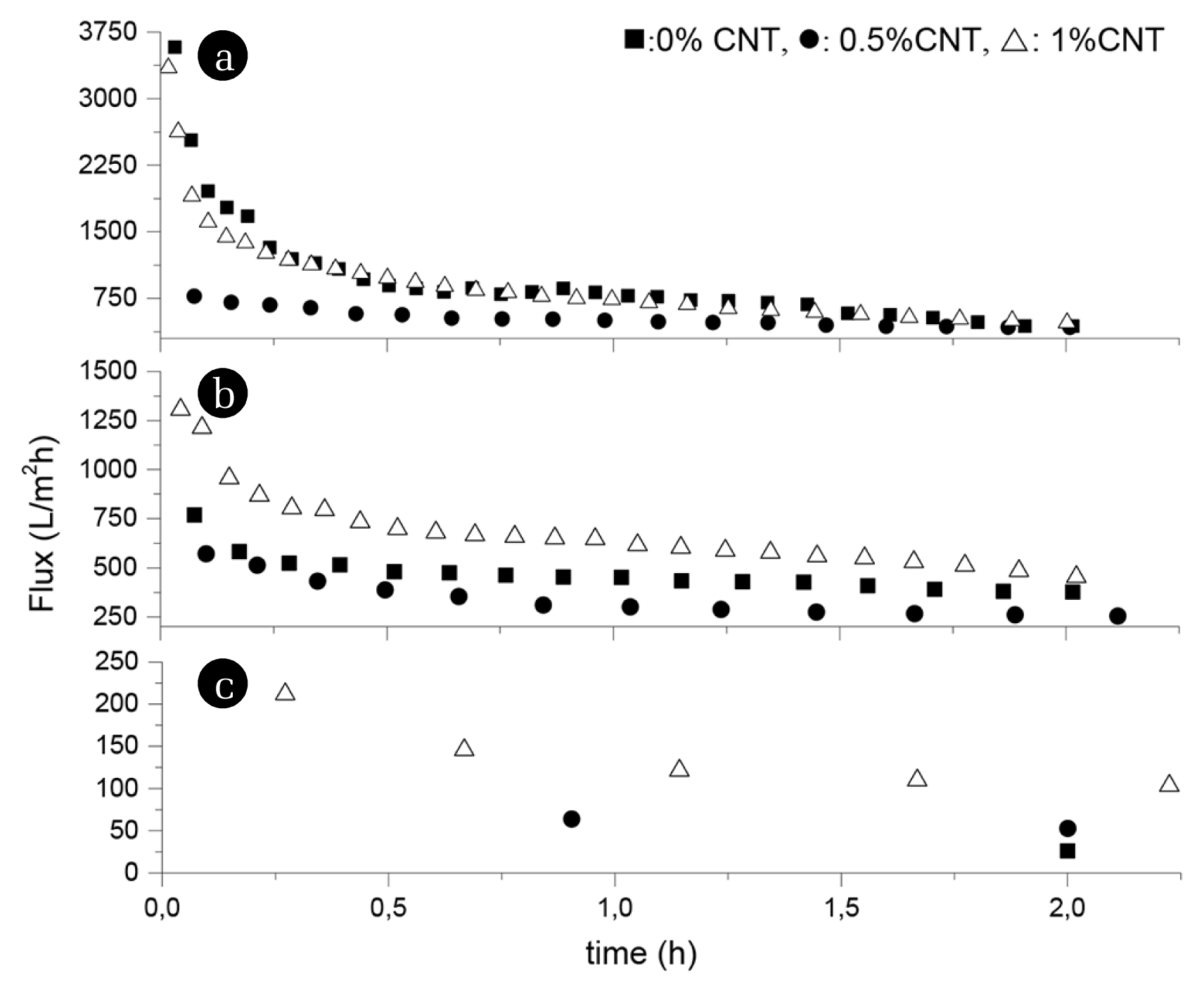
Pure water fluxes of the membranes (a) 10% PES, (b) 12% PES, (c) 15% PES.
One of the typical pollutants found in water treatment is protein-like substances [9, 52], which cause severe fouling during membrane filtration [52–55]. BSA was used as a model protein for determining the selectivity and fouling resistance. All membranes were subjected to filtration using 1 g/L BSA after 2 h of compaction, and the protein fluxes of the membranes were calculated using Eq. (4). The protein flux of the P-10:C-0, P12:C-0, and P15:C-0 at the end of 1 h BSA filtration were 78 L/m2h, 29 L/m2h, and 14 L/m2h, respectively. Consistent with the pore sizes and pure water flux of the membranes, the protein flux of the membranes decreased with increasing polymer amount. The protein flux of the P-10:C-1, P12:C-1, and P15:C-1 at the end of 1 h BSA filtration were 35 L/m2h, 45 L/m2h, and 17 L/m2h, respectively. Over 75% of pure water flux was lost at the end of 1 h BSA filtration in almost all membranes.
The protein rejections of the fabricated membranes are illustrated in Fig. 6. BSA rejections of the fabricated membranes increased with increasing PES or increasing CNT amount in the polymer solution. The smaller pores resulted in increased rejections.
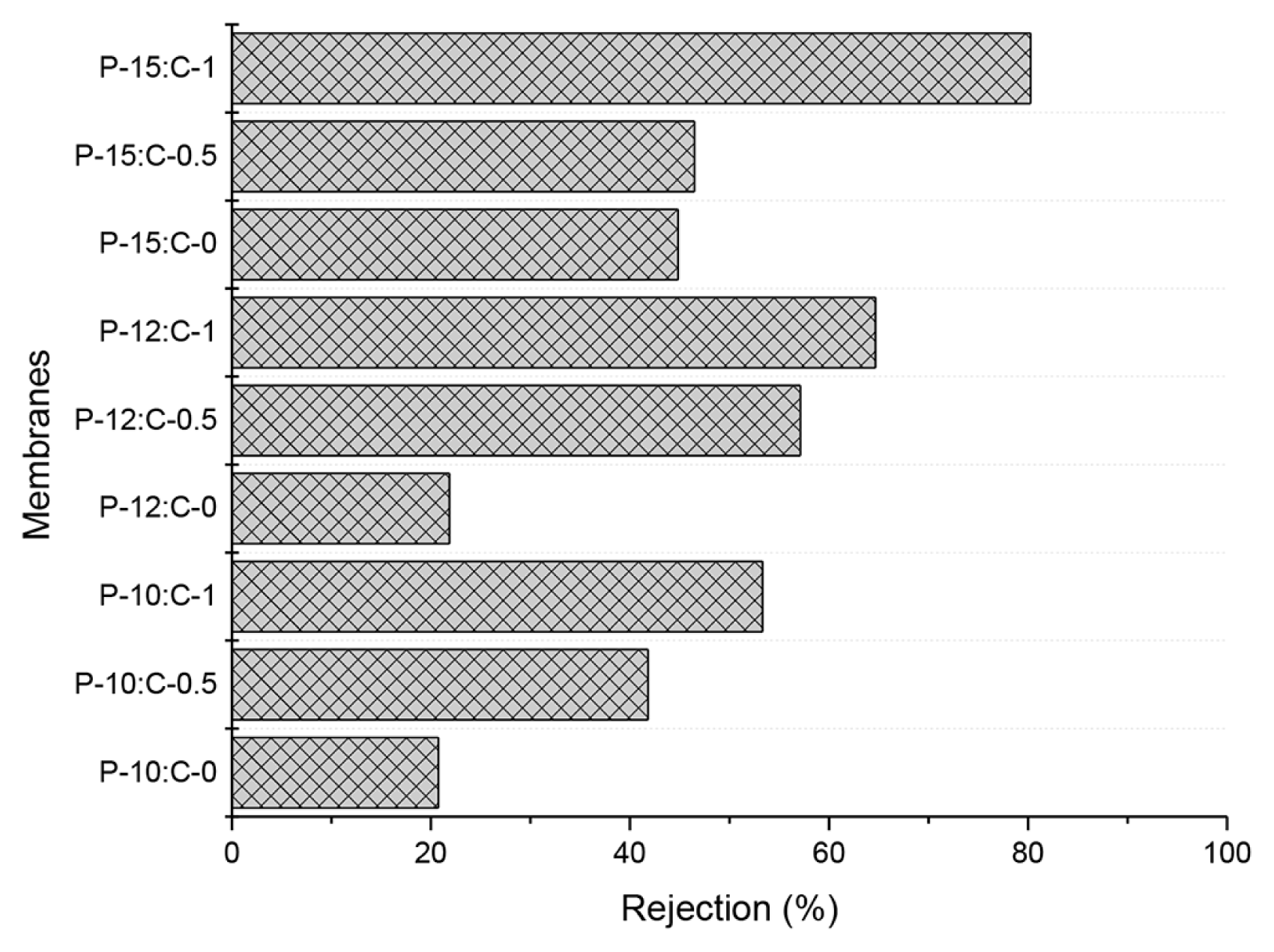
BSA rejection of fabricated membranes.
Hydraulic resistances (Table 2) of the membranes were examined to determine the fouling behaviors of the membranes. Hydraulic resistance develops in the virgin membranes (Rvm) due to the porosity, pore diameter, and cross-sectional framework. Hydraulic resistance of the membranes after filtration (Rfm) occurs because of fouling and concentration polarization [28, 56]. The hydraulic resistance of the membranes increased with 0.5% CNT addition in the polymer solution, but reduced with 1% CNT addition. That is, the fouling resistance of the membranes enhanced with increasing CNT amount in the polymer solution. Besides, increasing the PES amount in the polymer solution increased the hydraulic resistance of the membranes. The increased hydraulic resistance by increased PES amount might be because of the concentration polarization layer because of the increasing rejections. When high rejection with high flux is combined in the membrane operation, concentration polarization occurs. Hence concentration polarization is more severe in microfiltration and ultrafiltration operations [57, 58].
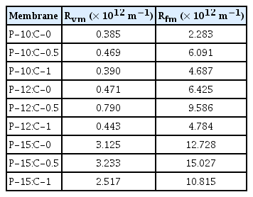
Hydraulic Resistances of the Fabricated Membranes
Considering the hydrophilicity, flux, porosity, and BSA rejection of the membranes, P-10:C-0, and P-12:C-0, showed quite similar properties. As a result, a 2% polymer difference did not result in a noteworthy difference in membrane properties. However, the P-15 membrane showed smaller pores, lower flux, higher BSA rejection than P-10:C-0 and P-12:C-0 membranes. Furthermore, CNT addition increased the hydrophilicity, flux, porosity, and BSA rejection in membranes with different polymer concentrations. CNT addition resulted in membranes with better membrane properties for all polymer concentrations.
4. Conclusions
Membranes with different polymer and CNT amounts were fabricated by the phase inversion method. Prior to fabrication, CNT functionalization was applied. TEM images and FTIR analysis of CNTs showed that the CNTs were shortened, the carbons at the defect sites, and the tips of the CNTs were converted to carboxylic groups.
There was more than a 10% increase in the hydrophilicity of the membranes with 1% CNT addition, but it was not altered with the polymer amount. Even though the porosity was increased 16% in P-15:C-1 compared to P-15:C-0, it was increased almost 30% in P-10:C-1 and P12:C-1 compared to P-10:C-0 and P12:C-0. The flux of P-15:C-1 is four times higher than P15:C-0. Moreover, the flux of the membranes reduced with increasing polymer amount (denser membrane structure) due to the reduced porosity. Consistent with the pore sizes of the membranes, BSA rejection enhanced with increasing polymer or CNT amount in the polymer solution. Besides, fouling resistance of the membranes decreased with increasing polymer amount but increased with increasing CNT amount because the concentration polarization and the hydraulic resistance of the membranes reduced with increasing CNT amount. That is, increasing the CNT amount in the polymer solution increased fouling resistances of the membranes, which is consistent with our previous findings. Membranes prepared with a higher amount of polymer concentrations are more prone to membrane property improvements by CNT addition. The increase in flux and selectivity by CNT addition for all polymer concentrations will increase the membrane life-time and reduce the treatment cost. A fundamental understanding of the effects of the polymer and CNT amount on the membranes can be achieved with this work.
Acknowledgment
Funding was provided by the Scientific and Technological Research Council of Turkey (Project No. 111R012) and Suleyman Demirel University (Project No. SDU-3785)
Notes
Author Contributions
E.C.M. (Assoc. Prof.) has supervised the study, prepared the figures and tables, written and revised the manuscript several times, and Z.I.C. (Master student) has conducted all the experiments.