Investigation of the thermodynamic performance of an existing steam power plant via energy and exergy analyses to restrain the environmental repercussions: A simulation study
Article information

Abstract
Exergy analysis is an important tool to identify the improvements in various industrial processes. In this study, the existing steam power plant is examined based on energy and exergy analyses. The steam network in the power plant is comprised of two sections, one of them is used for paddy drying, while other portion is used to operate the turbine for in-house electricity production. Mass, energy, and exergy balances are applied to individual equipment of the plant. The power plant is modeled and simulated using Aspen HYSYS® V10. The calculated thermodynamic values are used for in-depth analysis of the power plant. Case-studies are included in this study to show the effect of various operational parameters on the process efficiency. The analysis shows that the boiler is the major source of exergy destruction, because of the incomplete combustion process, and inappropriate insulations. The remedial actions are also suggested in the study.
1. Introduction
For the economic growth of a country, power generation companies play a vital role. A universally available form of energy is electrical energy, which can be converted into all other forms of energy and its demand has increased with time [1]. Powerhouses are installed in a considerable number in Pakistan for electrical energy generation, 75% of which are using coal as fuel. In these power plants, energy optimization is an important aspect regarding the decrease in the fuel consumption rate [2]. Energy consumption is an important parameter to reflect a country’s development stages and its communities living standards [3]. Power plant efficiency is a critical and important parameter regarding the decrease in fossil fuel consumption rate as it is a primary energy source for power generation, industry, and transportation [4]. However, in many countries, from power generation cycles, steam power cycles are now being rejected because of reduced efficiency, environmental pollution, depletion of fossil fuel resources, and are now replaced with comparatively more efficient, economical and cost-effective plants [5]. Fossil fuel plants are posing threats to increased depletion in resources of fossil fuels along with environmental deprivation. Many researchers in the world have done an investigation and have reached the conclusion that it is an intense need to shift the resources of power generation from non-renewable resources to renewables [6–8].
As the time is progressing, the aim is to shift the strategy towards the design of an efficient, consistent, and economical energy conversion system for low-temperature heat source utilization, which could not be utilized otherwise [9]. Up to 80% of the power generation facilities are utilizing fossil fuels (gasoline, natural gas, coal), and the remaining 20% of them are utilizing renewable assets (such as geothermal energy, nuclear power, dams, wind power, biomass, solar energy) [10]. For a country’s growth, sustainable development has become vital and plays a decisive role. Sustainable development is well-defined as the social development which is required in order to meet the present generations need without putting a risk at the needs of future generations [11–13]. Sustainable development demands that an industry, which is mainly based on non-renewable resources needs to be transformed into one based on renewable resources [14]. 1st and 2nd laws of thermodynamics can be effectively used for energy and exergy analysis, which provide information regarding heat losses & processes irreversibility [15].
Exergy analysis is a useful tool for the representation of variance among energy damages and internal irreversibility in the processes [16]. 1st law of thermodynamics is usually used for calculations of energy efficiency. However, the 1st law of thermodynamics is not enough to carry out the optimization of steam power cycles. Coupling of 1st law with the 2nd law of thermodynamics is required and is a useful tool regarding power system analysis in terms of energy and exergy. Exergy outlet can be defined as the system’s maximum useful output work. Exergy destruction/lost work can be defined as the sum of each component’s lost work in a power plant. Lost work can be estimated by tracking each individual equipment lost work and summing all these [17, 18]. During power plant operation, a part of the energy is rejected to the environment i.e., in surface condenser operation, saturated steam is condensed by heat exchange with cooling water pumping from the cooling tower, cooling water temperature is lowered by heat exchange with air, but the heat carried away with the air is not recovered and rejected to the environment. This type of energy is called Anergy [19].
Rankine cycle and combined cycle energy and exergy analysis were studied by Kaushik et al. [20] concluded that although condenser is the largest source for energy losses, boiler offers maximum exergy loss especially in the combustion processes, can happen due to incomplete combustion phenomena & insufficient insulation. The boiler of the steam power plant was analyzed on basis of energy and exergy by Khani et al. [21], concluded that exergy efficiency is increased to 0.19% & 0.37%, respectively as excess air fraction is decreased to 0.4 and 0.15. Furthermore, with the decrease in temperature of flue gases leaving the stack, from 137°C to 90°C, the increase in exergy efficiency was about 1.5%. Hamedan Steam power plant exergy study was done by Ameri et al. [22]. The analysis included the effect on total efficiency due to changes in environmental temperatures and unit loads. The authors concluded that % plant efficiency is increased if the air is preheated before sending into the boiler.
Equipment in HRSG of combined cycle power plants were analyzed based on energy and exergy analysis by Kaviri et al. [23]. Parameters investigated in the research comprised of the pressure of steam drum, and heat exchanger arrangements in HRSG for high and low-pressure parts. Combined cycle energetic, and exergy analyses were done by Ganjehkaviri et al. [24]. This combined cycle is associated with HRSG. For different components of the cycle, energetic, exergy and economic balances were applied. Based on the steam turbine exhaust, optimization was done for the plant. Energetic and exergy efficiencies were calculated as a function of the outlet vapor quality. The analysis showed that the optimized conditions of the system were achieved for the outlet vapor quality of 88%, consequently, decreasing the total operational cost of the cycle. Taillon and Blanchard [25] suggested new graphs for the determination of the exergy efficiency of thermal power plants. These graphs were helpful to determine the efficiency ranks as compared to the usually attained values for the industrial systems. Memon et al. [26] used three approaches/parameters for the thermodynamic study of a combined cycle power plant: exergo-economic, exergo-environmental, and statistics. Energy, exergy, and economic balances were applied to the complete system. The effect of operational conditions on the efficiencies (energy, exergy), power generation, and emissions was examined to obtain the optimized operational conditions of the plant. For the development of exergo-economic analysis, objective function is taken as the extension of exergy efficiency and minimization of total operating cost.
The present research aims to evaluate the efficiency of an operational power plant based on energy and exergy analyses. The model of the power plant is prepared, modeled, and simulated in Aspen HYSYS® V10. Exergy efficiency (%) and exergy destruction rate (kW) of individual equipment in the power plant are computed. Case studies are included in this study to analyze the effect of various operational parameters on the % efficiency of the various equipment.
2. Model Development
The power plant, under consideration, is operating on the principles of the Rankine and is installed in Pakistan. The model of the steam power plant is prepared/modeled and simulated in Aspen HYSYS® V10.
Fig. 1 represents the operational hierarchy of the power plant. The power plant consists of a rice processing facility for which a powerhouse section is installed in the plant premise for the electricity generation and steam supply to the rice-processing facility.

Schematic diagram of the steam power plant.
Underground raw water is pumped to the water storage tank using deep-well turbines. Water is pumped to the reverse osmosis plant (R.O.) for the removal of total dissolved and suspended solids. R.O. water is then pumped to the mixed bed polisher (MBP) unit for the preparation of demineralized water. Water at the outlet of MBP unit is suitable to be utilized as boiler feed water, as it contains very small fractions of solids, iron, and silica (in acceptable limits). However, dissolved oxygen (DO) cannot be removed from these sections. Therefore, water is the sent to de-aerator tank, where the DO removal takes place by counter-current contact with saturated steam (coming from low-pressure header). This saturated steam is supplied to the deaerator at 7 bar and 210°C. Water at the outlet of deaerator is termed as “boiler feed water (BFW)”, which is heated in the economizer (by heat exchange with flue gases coming from the furnace), and then to steam drum. The flue gases are produced in the combustion chamber due to the combustion of rice-husk as a fuel.
For the combustion process, both primary and secondary air are utilized, which are fed to the combustion chamber using two forced draft fans. The flue gases exchange heat in the following sequence: with the steam in two superheaters to produce superheated steam, water in the steam drum to produce saturated steam, boiler feedwater in the two economizers, and with the air in the air preheater. Since, ash is produced in this process, and flue gas may be carrying some ash with it, therefore, the scrubber is installed (at the downstream of the air preheater) to remove the ash contents from the flue gases by water spraying, and then is then vented at ambient conditions. Secondary air is preheated in the air-preheater and sent to the furnace.
Water enters the steam drum at 210 – 220°C and saturated steam is produced from the steam drum, which is converted to superheated steam in the superheaters. The superheated steam is divided into two streams/fractions; one of the fraction is sent to the low-pressure header, where saturated steam is produced, part of which is sent to the deaerator, while remaining part is sent to the rice processing facility, while second fraction is sent to the turbine, where superheated steam does work in the steam turbine, and the electricity is produced. The saturated steam leaves the turbine, which is condensed in the water-cooled condenser, and recycled to the deaerator tank. Cooling water (from the cooling tower) is used to condense the saturated steam in the condenser. The operational conditions of the steam power plant are presented in Table 1.
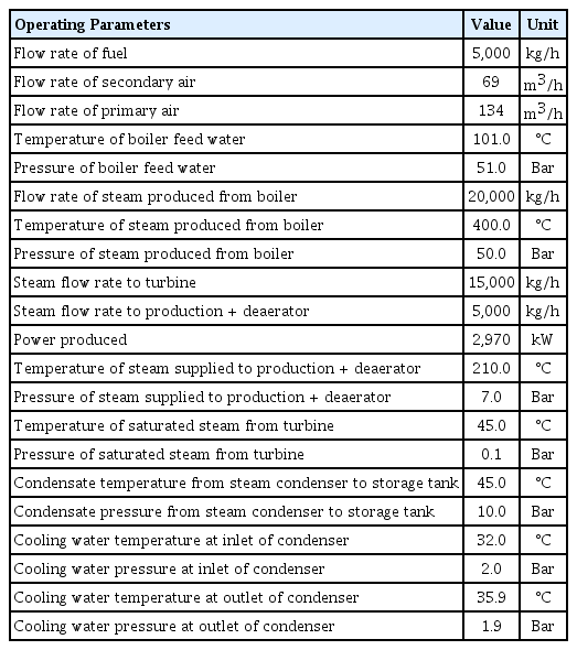
Operational Conditions of the Steam Power Plant
3. Analysis of The Equipment
For in-depth analysis of the steam power plant, following parameters are fixed:
Steady state
Kinetic and potential exergies are neglected.
Reference conditions (Po = 1 bar and To = 25°C).
The adiabatic system is considered for calculation purposes.
The thermodynamic property package selected for the system is “Peng-Robinson”. Thermodynamics parameters (enthalpy, and entropy) are calculated using Aspen HYSYS® V10 and are used in the detailed calculations of the steam power plant.
3.1. Boiler
The fuel used in the process is rice-husk. The chemical exergy of the fuel is released during the combustion in the boiler, which is transferred to the water. The power plant makes use of two types of rice husk, having a difference in calorific values, namely, new rice husk having a calorific value of 14,500 kJ/kg, and old rice husk having a calorific value of 13,700 kJ/kg. However, the analysis is carried out based on new rice husk as a fuel. To perform exergy analysis, the exergy flows are calculated for each stream, with specific enthalpy and entropy values calculated at reference conditions. For a boiler, exergy destruction (kW) and efficiencies (%) are calculated as follows:
3.1.1. Fuel exergy
The fuel used in the boiler is rice husk. For the calculation of fuel chemical exergy, its composition is required which is presented in Table S1.
Rosen [21] has quantified an equation that is helpful in calculating the chemical exergy of rice husk. Overall exergy of fuel can be calculated given the individual component’s standard chemical exergy and molar ratio.
where,
Nf = Mole fraction of each component in fuel
Ψch,f = Standard chemical exergy of each component in fuel
The chemical exergy values of individual components are presented in Table 2.

Chemical Exergy Values of Rice-Husk Components
3.1.2. Flue gases leaving from boiler
Flue gases (produced in the combustion chamber of the boiler) leaves the furnace at a temperature of 805.15 K. Since the gases are at high temperature, the temperature is reduced by heat exchange with boiler feed water which increases its temperature from 373.75 K to 493.15 K, while flue gases temperature reduces to 429.15 K. The flue gases come in countercurrent direct contact with raw water which removes the fly ash from the flue gas and flue gases leave the stack at a temperature of 313.15 K. For the demonstration of the chemical exergy of the combustion products, the equation was stated by Ahmadi and Toghraie [27], presented as follows:
Where,
ech,i = Individual component molar chemical exergy
xi = Individual component mole fraction of combustion product
3.1.3. Air entering the boiler
Primary and secondary airs are supplied to the combustion chamber by using forced draft fans. Secondary air is mainly used to spread the rice husk in the combustion chamber. Primary air is pre-heated to a temperature of 435.15 K and then fed to the combustion chamber. The composition of the air used in the process is presented in Table S2.
3.2. Turbine
The steam turbine is installed at the site to meet the electricity demands of the plant. The steam turbine can produce 2.97 MW (2970 kW) electricity. Superheated steam produced from the boiler at a temperature and pressure of 673.15 K and 50.5 bar respectively, enters the turbine, and its energy is utilized to produce work. The saturated steam leaves the steam turbine which is condensed in a condenser. The balances of the turbine are applied as follows:
Exergy Balance:
3.3. Condenser
Saturated steam leaving the turbine is condensed in the condenser by heat exchange with cooling water pumping from the cooling tower. By means of heat exchange, saturated steam condensed in the condenser, and is pumped to the deaerator. Cooling water is pumped back to the cooling tower where its temperature is reduced by the exchange of heat with ambient air. The balances on condenser are applied as follows:
Exergy Balance:
3.4. Pump
Seven pumps are installed in the steam power plant; two pumps (1 working + 1 standby) to pump condensate from water-cooled condenser to de-aerator, two pumps (1 working + 1 standby) to pump boiler feed water from deaerator to the economizer, three pumps (1 working + 2 standby) to pump raw water from raw water storage tank to the scrubber.
Win or Wpump values are taken on the operating condition to calculate % exergy efficiency. The exergy efficiency (%) formula for all pumps in the power plant is the same.
Exergy Balance:
3.5. Deaerator
Deaerator provides boiler feed water by allowing counter-current contact of water and steam, thus removing dissolved oxygen. Condensate from the water-cooled condenser and condensate from production (rice-processing facility) come in counter-current contact with steam, generated from the boiler. For the calculation purpose, the steam out through the deaerator is neglected.
Exergy Balance:
4. Results
Mass exergy values of the process stream are calculated using Aspen HYSYS® V10. Table 3 represents the detailed exergy analysis of the process. Various components i.e., primary forced draft fan, secondary forced draft fan, induced draft fan, boiler stop valve, etc. are neglected in this analysis due to negligible contribution towards % exergy destruction rate. Based on this energy analysis, the thermal efficiency of the boiler found to be 55.00 %. Based on exergy analysis, the exergy efficiency of the boiler is 55.90 %, with the overall plant exergy efficiency as 57.10%
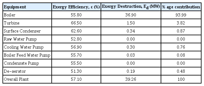
Exergy Efficiency (%) and Exergy Destruction Rate Calculation of Steam Power Plant
The % contribution to overall exergy destruction rate by each equipment is presented in Fig. 2. The analysis shows that boiler is the major source of exergy destruction i.e., 93.99%. The higher value of exergy destruction is caused due to various reasons i.e., incomplete combustion of rice husk in the furnace, poor air to fuel (rice husk) ratio and inappropriate insulations across heating parts. Rice husk combustion in a boiler, results in exergy consumption. This heat is transmitted to working fluid across larger difference of temperature. In a boiler, various heat exchange equipment i.e., primary, and secondary superheaters, economizers 1 & 2, air preheater are arranged in such a way to get maximum heat transfer from flue gas to preheat the incoming boiler feed water to steam drum to decrease fuel and air consumption.

Power plant equipment contribution towards total exergy loss of the system.
Thermal/Polytropic efficiency calculated for the steam turbine is 60.12%, while exergy efficiency is 66.50%. Two cooling water pumps are used for the flow of cooling water into the condenser. Cooling tower system is installed at a considerable distance from other utility section. This has led to an increase in the cooling tower power requirements as two pumps are required for the supply of the adequate cooling water flow. This parameter has increased the power requirements, and subsequently the utility costs. If this is replaced with a single cooling water pump with a high flow rate pump, which will not only decrease in cost but will increase the % exergy efficiency of the plant.
Various case studies are carried out on Aspen HYSYS® V10 to analyze the effect of operational parameters on the performance of the system, which are presented as follows:
4.1. Case Study-1
Fig. 3 represents the effect of primary air temperature on the combustion. The analysis shows that there is nearly a linear relationship between primary air temperature and flue gas production rate. Primary air, before entering the boiler, is passed through the air preheater where it takes heat from the flue gases coming from economizer 1. As the temperature of the primary air is increased, the production rate of flue gases increases showing that the increase in temperature has contributed towards an increase in the combustion efficiency. The comparatively reduced amount of carbon is un-combusted, decrease in ash/residue production rate which helps in improved % exergy efficiency of the boiler. This case-study is also in agreement with the research conducted by various researchers [20, 27–30].
Effect of primary air temperature on production of flue gases and ash in the boiler.
4.2. Case Study-2
Fig. 4 represents the effect of properties of superheated steam temperature (at the turbine inlet) on the polytropic efficiency of the turbine. The analysis shows that with the increase in steam temperature from 350 to 450°C, a 3% increase in polytropic efficiency is observed. Increase in temperature of the system results in the increase in the superheating degree, which leads to the improved operational efficiency of the steam turbine. This case-study is also in agreement with the research conducted by various researchers [27, 29, 30].

Influence of superheated steam parameters on steam flow rate.
4.3. Case Study-3
Fig. 5 represents the effect of superheated steam temperature and pressure on the steam requirements by the steam turbine, keeping electricity production capacity same i.e., 2.97 MW. The analysis shows that with the increase in temperature and pressure of the superheated steam (from the boiler), the steam flowrate requirement is decreased. This case-study is also in agreement with the research conducted by various researchers [27, 29, 30].
Effect of superheated steam properties on steam turbine operating efficiency.
5. Conclusions
The objective of the work was to evaluate the performance of the steam power plant based on energy and exergy analyses. The exergy analysis shows that the boiler is the major source of exergy destruction rate in the process, mainly due to incomplete combustion, inappropriate air to fuel ratio, inappropriate insulations. It is recommended to install the variable flowmeters on the air stream and apply an interlock control scheme with incoming feed for maintaining effective fuel to air ratio. Insulation across the furnace and heating parts needs to be improved as it is another factor towards the increase in the exergy destruction rate through the boiler. The % exergy destruction rate associated with the steam turbine is 3.81%, because the turbine is operating below the design specifications i.e., 61 bar is the design pressure, while the steam turbine is operating at 50 bar, which is causing decrease in thermal and exergy efficiency. Operating cooling tower with a single pump can result in improved exergy efficiency of the plant. It will result in improved exergy efficiency of the overall plant, eventually resulting in an improved cost of the plant.
Supplementary Information
Nomenclature
BFW
Boiler feed water
Ed
Exergy destruction (kW)
MBP
Mixed bed polisher
Po
Reference pressure (Bar)
R
Ideal gas constant
R.O.
Reverse osmosis
W
Work produced (turbine) or work consumed (pump)
To
Reference temperature (°C)
Greek Letters
ɛ
Exergy efficiency (%)
xi
Mole fraction of component, i
ech,i
Individual component molar exergy value
Subscripts
1
Steam at the inlet of turbine
2
Steam at the outlet of turbine
3
Cooling water at the inlet of condenser
4
Cooling water at the outlet of condenser
5
Condensate at the outlet of condenser
6
Stream at the pump inlet
7
Stream at the pump outlet
8
Polished water from the mixed bed polisher
9
Saturated steam from the low-pressure header
10
Recovered condensate from paddy section
11
Boiler feed water inlet to the boiler
Acknowledgments
The authors are thankful to the Department of Chemical Engineering, COMSATS University Islamabad, Lahore Campus, for providing licensed version of Aspen HYSYS® V10. The financial support from the University of Seoul and National Research Foundation under the project (NRF- 2020R1I1A1 A01072793) is gratefully acknowledged to conduct this research.
Notes
Author Contributions
M.H.H. (Lecturer, Ph.D) and I.S. (Ph.D) wrote the manuscript and conducted the simulation study. A.A. (Research Professor) performed the data analysis. M.H. (Professor) and Y.-K.P. (Professor) planned the study and revised the manuscript.