This is an Open Access article distributed under the terms of the Creative Commons Attribution Non-Commercial License (http://creativecommons.org/licenses/by-nc/3.0/) which permits unrestricted non-commercial use, distribution, and reproduction in any medium, provided the original work is properly cited.
Abstract
Although membrane distillation (MD) has great promise for desalination of saline water sources, it is crucial to improve its thermal efficiency to reduce the operating cost. Accordingly, this study intended to examine the thermal energy efficiency of MD modules in a pilot scale system. Two different modules of hollow fiber membranes were compared in direct contact MD mode. One of them was made of polypropylene with the effective membrane area of 2.6 m2 and the other was made of polyvinylidene fluoride with the effective membrane area of 7.6 m2. The influence of operation parameters, including the temperatures of feed and distillate, feed flow rate, and distillate flow rate on the flux, recovery, and performance ratio (PR), was investigated. Results showed that the two MD membranes showed different flux and PR values even under similar conditions. Moreover, both flow rate and temperature difference between feed and distillate significantly affect the PR values. These results suggest that the operating conditions for MD should be determined by considering the module properties.
Membrane technology is a highly efficient separation technique compared with other physicochemical water treatment technologies [1]. Depending on its driving force, there are several different cases, including pressure-driven membrane processes, concentration-driven membrane processes, electrically-driven membrane processes, and thermally-driven membrane processes [2]. Among them, membrane distillation (MD), which is one of the temperature-driven separation techniques, has drawn attention as a novel option for seawater desalination and wastewater treatment [3]. Unlike conventional thermal distillation, which uses a huge amount of thermal energy, MD can utilize heat sources of low grade such as waste heat from industrial plants [4] and solar heat [5–6] due to its capability of low-temperature operation [7]. In MD, various methods are applied to put a vapor pressure difference through a membrane for production of water (or vapor) flux [8]. In direct contact membrane distillation (DCMD), condensing fluid passes through the permeate side of the membrane, and in sweeping gas membrane distillation (SGMD), condensing gas flows in the permeate side of the membrane. In air gap membrane distillation (AGMD), an air gap separates a condensing surface from the membrane by AGMD, and in vacuum membrane distillation (VMD), vacuum exists between the membrane and the condenser [8, 9]. In general, the DCMD configuration, which is the simplest configuration with the capability of easy operation, is known as a suitable technology for water treatment application [9–11].
During MD, thermal energy is transferred from feed water to distillate together with water vapor [8, 12]. At the same time, conductive heat loss and dissipation of heat to outer environment may occur, leading to a reduction in thermal energy efficiency of MD [13]. Although MD uses low grade thermal energy, which is cheaper than conventional thermal energy such as high-pressure steam, it is still important to increase thermal energy efficiency to reduce operation cost and increase the throughput (water production) of MD [14].
There have been a lot of works on MD, including membrane preparation [1, 15], fouling control [16, 17], wetting control [18], and process modelling [19, 20]. However, relatively few works have been attempted to understand the thermal efficiency of MD module or MD system [13]. Moreover, previous experiments were mostly carried out using laboratory-scale MD equipments, which cannot fully represent the characteristics of pilot-scale or full-scale MD processes [21].
In this context, this study aimed at the investigation of thermal efficiency of MD modules in pilot-scale systems, which provides insight into understanding cost-effective process design for full-scale MD processes. The originality of this study lies on; (1) the analysis of thermal efficiency in hollow fiber MD modules in pilot-scales; and (2) the investigation on the factors affecting the thermal efficiency of the MD modules.
2. Materials and Methods
2.1. MD Module
Two different hollow fiber MD membrane modules were used to compare their flux and thermal efficiency. In Table 1, the properties of these MD modules are summarized. Due to the request by the membrane manufacturers, the membrane modules are denoted as membrane ‘A’ and membrane ‘B’, respectively. These two membrane modules were made of different materials and had different fiber and module dimensions. The membrane ‘A’ was made of polypropylene (PP) and the other membrane ‘B’ was made of polyvinylidene fluoride (PVDF). The inner diameter and outer diameter of the membrane ‘A’ are 4.0 × 10⁻⁴ m and 6.6 × 10⁻⁴ m, and those of the membrane ‘B’ are 8.0 × 10⁻⁴ m and 1.2 × 10⁻³ m, respectively. In this case, the length of the module of membrane ‘A’ is 0.74 m and ‘B’ is 0.84 m. The shell diameter of membrane ‘A’ is 0.11 m and ‘B’ is 0.29 m. Membrane area per module of membrane ‘A’ is 2.6 m2 and it of membrane ‘B’ is 7.6 m2.
2.2. Pilot-scale MD System
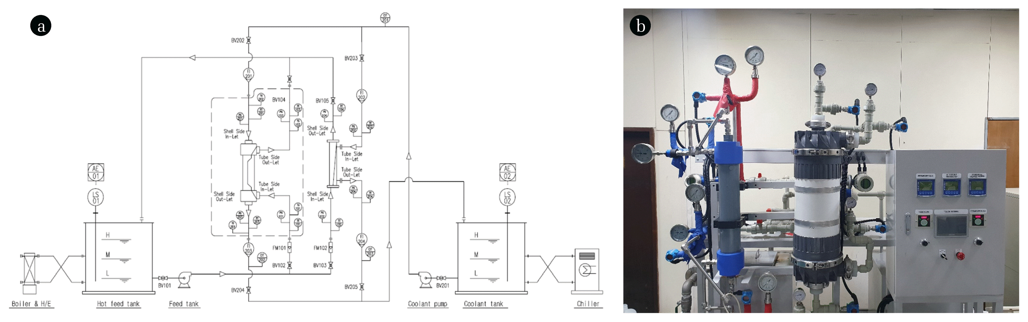
The process schematics and picture of the pilot-scale MD system are illustrated in Fig. 1. The system consists of a feed tank, a distillate tank, recirculation pumps, MD modules, a heater, and a cooler. Prior to be supplied to the MD module, the temperature of the feed water was controlled by using the heater and the temperature sensor. The temperature of the distillate flowing into the MD module was controlled by using the cooler and the temperature sensor. Although it was difficult to set the temperature to a certain value, it was possible to maintain the temperature constant during the operation. The maximum capacity of the system is about 2.74 kg/m2-h.
Since the two MD modules had different flow configurations, the feed and distillate were supplied in different ways. In the membrane ‘A’ module, the feed water was supplied to the tube side and the distillate water flowed through the shell side (“Inside-out”). In the membrane ‘B’ module, the feed water was supplied to the shell side and the distillate water flowed through the tube side (“Outside-in”). The temperatures of feed inlet, feed outlet, distillate inlet, and distillate outlet were continuously monitored, which were used to calculate an energy balance in each case. Moreover, an electronic balance was used to measure the changes in the weight of the distillate water, which were used to calculate MD flux.
The MD experiments were carried out under various operating conditions. The feed flow and distillate flow rates were controlled from 0.54 m3/h to 2.7 m3/h. The feed inlet temperature had a range from 59.1°C to 79.26°C and the distillate inlet temperature had a range from 20.65°C to 31.08°C. The tap water was used in the feed water because the purpose of this study was the analysis of thermal efficiency in MD systems. Nevertheless, the rejection of the membrane was regularly checked before and after the experiments. Details on the experimental conditions were summarized in Table 2.
3. Results and Discussion
3.1. MD Flux and Temperature Differences
3.1.1. Membrane ‘A’
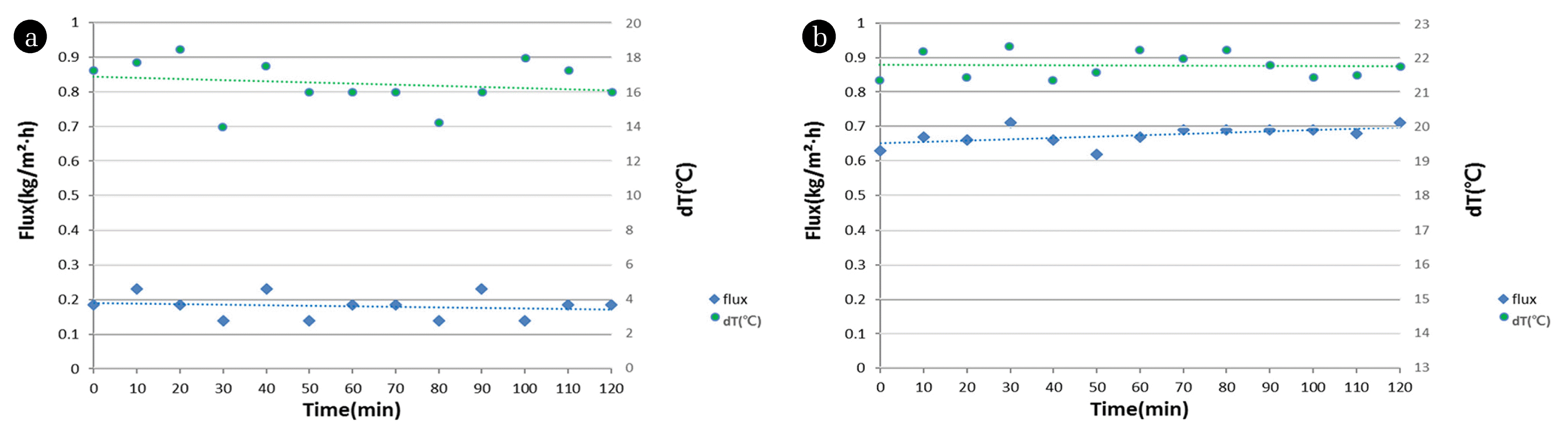
The MD flux and the temperature difference between the feed and distillate are shown as a function of operation time in Fig. 2(a). The feed and distillate temperatures were 59.7°C and 30.84°C, respectively and the feed and distillate flow rates were 0.9 m3/h and 0.6 m3/h, respectively. The average flux was 0.21 kg/m2-h with the temperature difference ranging from 14°C to 18.5°C. To understand the relationship between vapor pressure and temperature, the Antoine equation is used [13]:
(1)
where p is the vapor pressure (mmHg), T is temperature (°C), and A, B, and C are component-specific constants, which corresponds to 8.07131, 1730.63, and 233.426, respectively. This equation can be applied in the temperature range between 1°C and 99°C. According to this equation, the vapor pressures of the pure water at 59.7°C and 30.84°C are 0.1960 bar and 0.0444 bar, respectively. Therefore, the apparent water vapor permeability of membrane module ‘A’ is calculated to 1.39 kg/m2-h-bar, which is the ratio of flux to applied vapor pressure difference. The intrinsic water vapor permeability of the membrane may be different from this because the net temperature difference across the membrane is different due to temperature polarization and other heat transfer resistances.
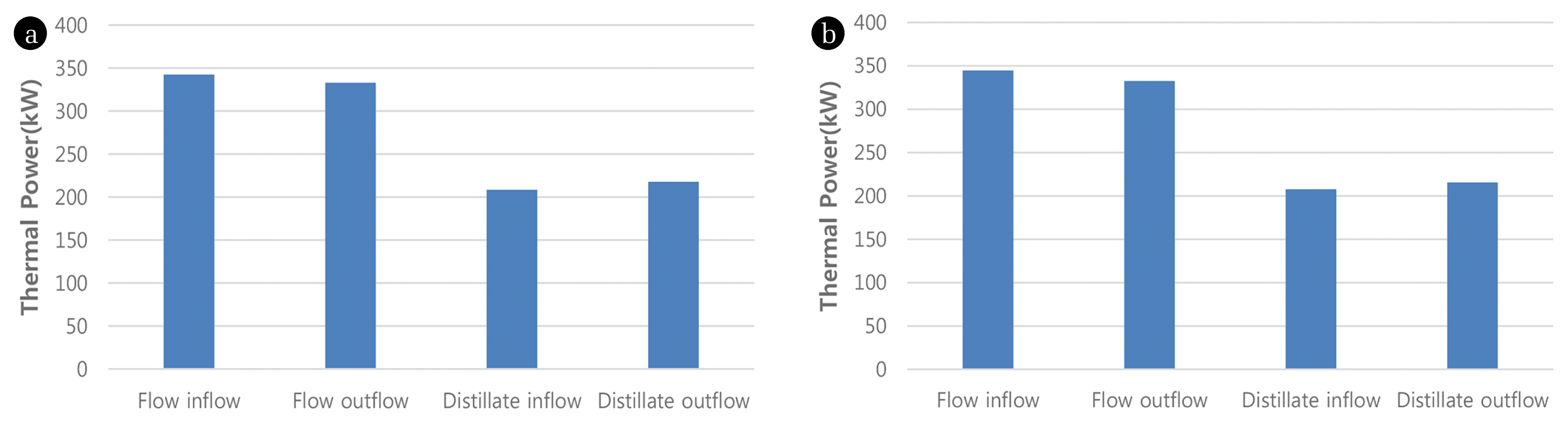
Using the flow rate and temperature, the amount of thermal energy at the inlet and outlet of the membrane module can be calculated. The results are illustrated in Fig. 3(a). The thermal energy at the inlet of the feed is always higher than that at the outlet of the feed. On the other hand, the thermal energy at the inlet of the distillate is always lower than that at the outlet of the distillate. In fact, the temperature difference between feed inflow and feed outflow was 9.5°C and the temperature difference between distillate inflow and distillate outflow was 9.2°C. This suggests that the thermal energy supplied from the feed side of the membrane module is transferred to the distillate side.
3.1.2. Membrane ‘B’
The changes in MD flux and the temperature difference between the feed and distillate with time are presented in Fig. 2(b). The feed and distillate temperatures were 60.73°C and 29.79°C, respectively and the feed and distillate flow rates were 0.9 m3/h and 0.6 m3/h, respectively. The average flux was 0.67 kg/m2-h with the temperature difference ranging from 21°C to 22.35°C. A slight increase in flux with constant temperature difference may be attributed to the experimental errors from the instruments such as digital thermometer and the electronic balance.
Using the Eq. (1), the water vapor permeability for the membrane module ‘B’ was calculated, which is 4.09 kg/m2-h-bar. It should be noted that the two modules showed different flux and permeability under similar operating conditions. It is evident from these results that the design of MD module is of great importance.
In Fig. 3(b), the thermal energy values at the inlet and outlet in feed and distillate sides are shown for membrane module ‘B’. Compared with the case of membrane module ‘A’, the difference between feed inlet and feed outlet increased and the difference between distillate inlet and distillate outlet decreased. In fact, the temperature difference between feed inflow and feed outflow was 11°C and the temperature difference between distillate inflow and distillate outflow was 7.7°C, which supports the results of thermal energy calculation.
Aside from the flux, the membrane module ‘B’ has an additional advantage over the membrane module ‘A’ due to the difference in the membrane materials. The fibers of the membrane module ‘B’ were made of PVDF, which has moderate thermal stability, good chemical resistance with a surface energy of 30.3 × 10⁻³ N/m [5]. On the other hand, the fibers of the membrane module ‘A’ were made of PP, which has a lower membrane performance due to their moderate thermal stability at elevated temperatures and a slightly lower surface energy of 30.0 × 10⁻³ N/m [6].
3.2. Analysis of Performance Ratio (PR)
Using the results of the MD experiments, the thermal energy balance was established through the following steps. First, the energy supplied to the MD system should be broken down into three terms [6, 7, 9].
(2)
where Qin is the energy input to the MD system, Qflux is the energy used for flux, Qcond is the energy lost by heat conduction through the membrane, and Qloss is the other thermal energy loss from water tank, pipe, and other part. Qin and Qflux are given by [8, 9]:
(3)
(4)
(5)
(6)
Where ρ is the water density, qf,in is the feed inflow rate, qf,out is the feed outflow rate, qd,in is the distillate inflow rate, qd,out is the distillate outflow rate, Cp is the heat capacity of water, Tf,in is the feed inlet temperature, Tf,out is the feed outlet temperature, Td,in is the distillate inlet temperature, Td,out is the distillate outlet temperature, Hw is the latent heat of water vaporization, Am is the membrane area, and Jw is the distillate flux.
The performance ratio (PR), which is defined as the ratio of the thermal energy used for evaporation to the total thermal energy input, is an index to measure the thermal efficiency for distillation systems. Accordingly, it is important to increase PR to reduce the cost for the thermal energy for MD. In a single stage distillation, PR is less or equal to 1.0 and in a multi-stage distillation, PR is proportional to the number of stages. In a single stage DCMD system, PR can be given by:
(7)
In Eq. (7)Qin is the thermal energy supplied to the MD module. Accordingly, Qin/Hw corresponds to the amount of “virtual steam” supplied to the MD module (m3/s). This is “virtual” because the thermal energy is not supplied as the form of real steam in DCMD. On the other hand, JwAm (m3/s) is the amount of fresh water produced using the “virtual steam” of Qin/Hw (m3/s). Accordingly, the ratio of JwAm to Qin/Hw may correspond to the mass ratio of water produced to “virtual steam supplied”.
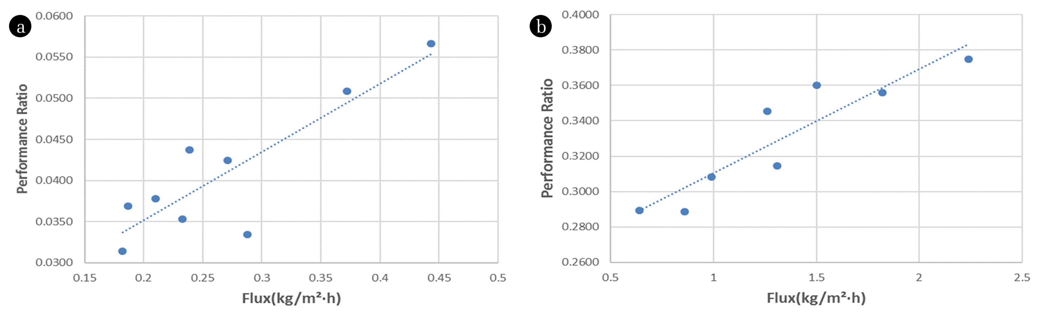
Table 2 shows the results of flux and PR in each experimental condition with the membrane ‘A’ and ‘B’. The membrane module ‘A’ had the PR ranging from 0.0314 to 0.0566. In other words, only 3–5% of the thermal energy was used to produce distillate, which is not efficient. This is mainly attributed to its low flux (0.18–0.44 kg/m2-h) and heat loss through the membrane, module and pipes. As the feed temperature increases, the flux increases, leading to an increase in the PR. The feed flow rate also affects the flux and the PR. In other words, the PR increases with an increase in the flux.
The membrane module ‘B’ had high PR values, which range from 0.289 to 0.375. As mentioned above, this is attributed to higher flux for this membrane module. However, it is likely that flux is not the only factor affecting the PR. The highest flux for the membrane ‘A’ was 0.443 kg/m2-h with the PR of 0.0556. The lowest flux for the membrane ‘B’ was 0.64 kg/m2-h with the PR of 0.289. Although the flux ratio between two membranes was 0.692, the PR ratio was 0.0192. These results suggest that the membrane module ‘A’ had higher heat losses though the membrane and other parts than the membrane module ‘B’.
3.3. Correlation between Flux and PR
It is important to understand which factors affect the thermal efficiency of the MD process. Accordingly, correlations between process parameters and PR were analysed. In Fig. 4, the PR was shown as a function of flux for the membrane module ‘A’ and ‘B’. As expected, the PR linearly increases with the flux. Accordingly, it is concluded that the thermal energy efficiency in DCMD can be improved by increasing flux. However, the deviations of the data pointing from the regression line indicate there are also other factors affecting the thermal efficiency of the MD system. This is because thermal efficiencies for different MD modules cannot be simply compared in terms of flux. Accordingly, high thermal efficiency of DCMD system can be achieved by not only improving flux but also reducing heat losses with the development of new modules and technologies.
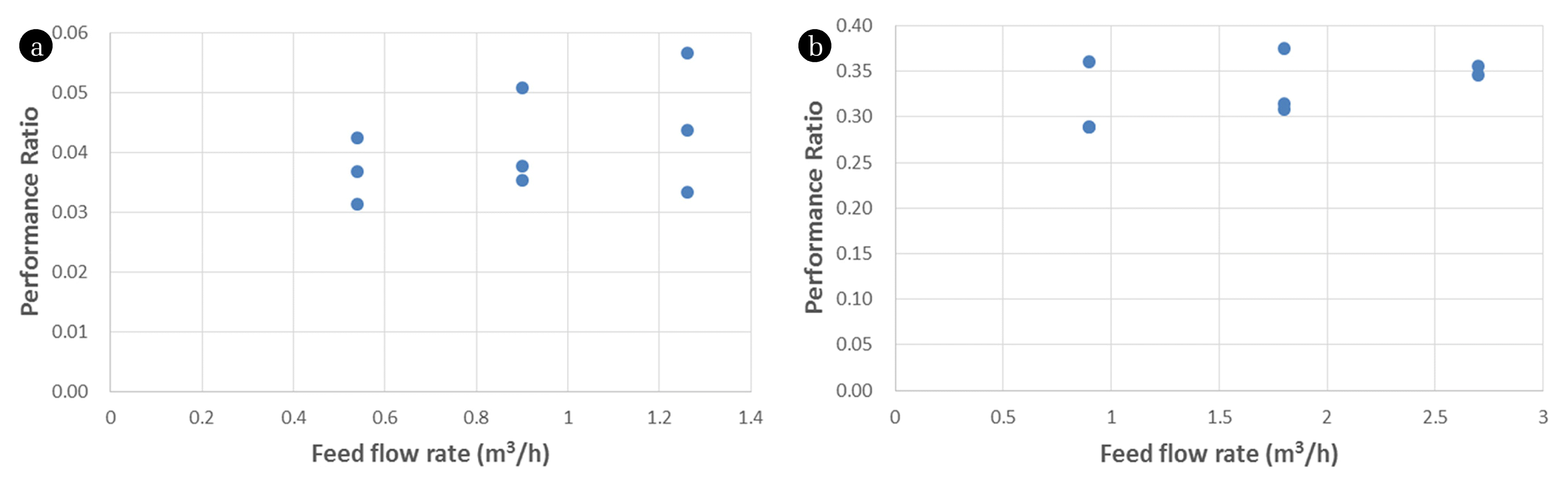
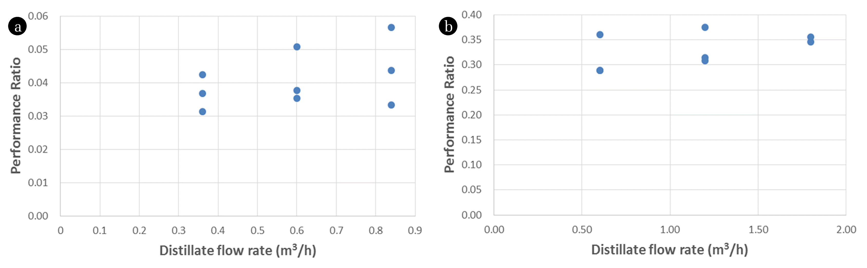
As shown in Fig. 5 and Fig. 6, the PR did not show strong correlations with the flow rates of feed and distillate streams. This suggests that the flow rates are not important factors affecting the thermal efficiency of the MD process. An increase in the feed flow rate may lead to an increase in the supply of thermal energy. However, it cannot be used if the flux through the membrane is not enough. Accordingly, the PR is more dependent on the flux than the feed flow rate. In a similar reason, the distillate flow rate is less important than the flux.
4. Conclusions
In this study, the energy efficiency in a pilot-scale DCMD system was analyzed for two different hollow fiber MD modules. Key performance factors such as flux and PR were examined as a function of operation parameters. The following conclusions were withdrawn:
Although the operating conditions were similar, the two membrane modules resulted in different flux, which may be attributed to membrane materials, properties, and module geometry and flow patterns. The difference in flux also affected the heat transfer through the membrane.
The energy balance for the DCMD system was established to understand the heat flows and energy efficiency. The PR, which represents the thermal efficiency, is found to be highly dependent on the flux. The PR is almost linearly proportional to the flux. Accordingly, the thermal energy efficiency in DCMD should be improved by increasing flux.
However, not only the flux but also other factors such as heat losses affects the PR. Accordingly, the thermal efficiencies for different MD modules cannot be directly compared in terms of flux.
Acknowledgments
This work is supported by the Korea Agency for Infrastructure Technology Advancement (KAIA) grant funded by the Ministry of Land, Infrastructure and Transport (Grant 18IFIP-B116951-03).
References
1. Le NL, Nunes SP. Materials and membrane technologies for water and energy sustainability. Sust Mater Technol. 2016;7:1–28.
2. Subramani A, Jacangelo JG. Emerging desalination technologies for water treatment: A critical review. Water Res. 2015;75:164–187.
3. Thomas N, Mavukkandy MO, Loutatidou S, Arafat HA. Membrane distillation research & implementation: Lessons from the past five decades. Sep Purif Technol. 2017;189:108–127.
4. Hagedorn A, Fieg G, Winter D, Koschikowski J, Mann T. Methodical design and operation of membrane distillation plants for desalination. Chem Eng Res Design. 2017;125:265–281.
5. Charcosset C. A review of membrane processes and renewable energies for desalination. Desalination. 2009;245:214–231.
6. Al-Karaghouli A, Kazmerski LL. Energy consumption and water production cost of conventional and renewable-energy-powered desalination processes. Renew Sust Energ Rev. 2013;24:343–356.
7. Drioli E, Ali A, Macedonio F. Membrane distillation: Recent developments and perspectives. Desalination. 2015;356:56–84.
8. Alkhudhiri A, Darwish N, Hilal N. Membrane distillation: A comprehensive review. Desalination. 2012;287:2–18.
10. Wang P, Chung TS. Recent advances in membrane distillation processes: Membrane development, configuration design and application exploring. J Membrane Sci. 2015;474:39–56.
11. Deshpande J, Nithyanandam K, Pitchumani R. Analysis and design of direct contact membrane distillation. J Membrane Sci. 2017;523:301–316.
12. Ashoor BB, Mansour S, Giwa A, Dufour V, Hasan SW. Principles and applications of direct contact membrane distillation (DCMD): A comprehensive review. Desalination. 2016;398:222–246.
13. Zhang Y, Peng Y, Ji S, Li Z, Chen P. Review of thermal efficiency and heat recycling in membrane distillation processes. Desalination. 2015;367:223–239.
14. Ali E. Energy efficient configuration of membrane distillation units for brackish water desalination using exergy analysis. Chem Eng Res Design. 2017;125:245–256.
15. Eykens L, De Sitter K, Dotremont C, Pinoy L, Van der Bruggen B. Membrane synthesis for membrane distillation: A review. Sep Purif Technol. 2017;182:36–51.
16. Tijing LD, Woo YC, Choi JS, Lee S, Kim SH, Shon HK. Fouling and its control in membrane distillation – A review. J Membrane Sci. 2015;475:215–244.
17. Abid HS, Johnson DJ, Hashaikeh R, Hilal N. A review of efforts to reduce membrane fouling by control of feed spacer characteristics. Desalination. 2017;420:384–402.
18. Rezaei M, Warsinger DM, Lienhard VJH, Samhaber WM. Wetting prevention in membrane distillation through super-hydrophobicity and recharging an air layer on the membrane surface. J Membrane Sci. 2017;530:42–52.
19. Liu J, Liu M, Guo H, Zhang W, Xu K, Li B. Mass transfer in hollow fiber vacuum membrane distillation process based on membrane structure. J Membrane Sci. 2017;532:115–123.
20. Hitsov I, Maere T, De Sitter K, Dotremont C, Nopens I. Modelling approaches in membrane distillation: A critical review. Sep Purif Technol. 2015;142:48–64.
21. Woldemariam D, Kullab A, Fortkamp U, Magner J, Royen H, Martin A. Membrane distillation pilot plant trials with pharmaceutical residues and energy demand analysis. Chem Eng J. 2016;306:471–483.
Fig. 1
Pilot-scale DCMD system (a) schematic diagram, (b) photograph.
Fig. 2
Variation in flux and temperature difference between feed and distillate in DCMD operation with (a) Membrane ‘A’ (Conditions: feed temperature, 59.7°C; distillate temperature, 30.84°C; feed flow, 0.9 m3/h; distillate flow, 0.6 m3/h), (b) Membrane ‘B’ (Conditions: feed temperature, 60.73°C; distillate temperature, 29.79°C; feed flow, 0.9 m3/h; distillate flow, 0.6 m3/h).
Fig. 3
Water and energy balances for direct contact MD system with (a) Membrane ‘A’ (Conditions: feed temperature, 59.7°C; distillate temperature, 30.84°C; feed flow, 0.9 m3/h; distillate flow, 0.6 m3/h), (b) Membrane ‘B’ (Conditions: feed temperature, 60.73°C; distillate temperature, 29.79°C; feed flow, 0.9 m3/h; distillate flow, 0.6 m3/h).
Fig. 4
PR versus flux in DCMD process with (a) Membrane ‘A’, (b) Membrane ‘B’.
Fig. 5
PR versus feed flow rate in DCMD process with (a) Membrane ‘A’, (b) Membrane ‘B’.
Fig. 6
PR versus distillate flow rate in DCMD process with (a) Membrane ‘A’, (b) Membrane ‘B’.
Table 1
Properties of MD Membrane Modules
Parameters
Membrane A
Membrane B
Membrane material
PP (Polypropylene)
PVDF (Polyvinylidene Fluoride)
Shell diameter
0.11 m
0.29 m
Fiber inside diameter
4.0 × 10⁻⁴ m
8.0 × 10⁻⁴ m
Fiber outside diameter
6.6 × 10⁻⁴ m
1.2 × 10⁻³ m
Nominal pore size
1.0 × 10⁻⁷ m
1.0 × 10⁻⁷ m
Porosity
0.6
0.8
Module length
0.74 m
0.84 m
Membrane area per module
2.6 m2
7.6 m2
Table 2
Results of Flux and Performance Ratio in Each Experimental Condition