1. Introduction
Recently, various studies have been conducted that explore methods to reduce fine dust as increasing fine dust concentrations in the environment have become a serious global concern. Volatile organic compounds (VOCs) are one of the main fine dust precursors and contribute significantly to the generation of fine dust [1]. VOCs are emitted by various solids and liquids in our living and working environments and high concentrations or long-term exposure pose a significant health risk [2]. Methods investigated to reduce VOCs involve adsorption [3–6], photocatalytic decomposition [7,8], catalytic oxidation [1,2,9–15], and non-thermal plasma. A disadvantage of adsorption methods is the necessity for the periodic post-process treatment of spent adsorbents involving the desorption of captured VOCs or regeneration of the adsorbent [16,17]. Catalytic oxidation methods have the advantages of long-term operation—due to the comparatively high chemical durability of the catalytic materials—and relatively low post-process costs for regeneration of catalysts; however, the material costs of these catalytic materials exceed those of the adsorbents, and the heating process for the catalytic reaction is essential.
Transition metal–oxide (TMO) catalysts [18,19] are less expensive than noble-metal catalysts and exhibit adequate catalytic activity. Oxide catalysts generally have a high activation temperature; however, the activation temperature and efficiency of oxide catalysts can be reduced and increased, respectively, by modifying their crystallinity [14,15,20] and nanostructures [7] or incorporating a small number of noble-metal nanostructures TMOs catalysts have been investigated to remove pollutants under low temperature because of their high catalytic behavior at low temperature [21–23]. MnO2 is considered a representative TMO material with various forms; however, MnO2 nanocrystals, in particular, show high catalytic activity toward VOC decomposition and a low activation temperature (≤250 °C) [15,24,25].
Recent studies have reported that the catalytic activities of noble metal–TMO composites exceed those of corresponding TMOs because of interactions between the noble-metal and transition-metal components. In addition, the morphology of the TMO in noble metal–TMO composites affects the particle size and dispersion of the noble metal, and as a result, the catalytic behavior of the composite. For example, Li et al. found that the morphology of MnO2 (nanowire-like, nanorod-like, and nanotube-like structures) in Ag/MnO2 catalysts affects the catalytic oxidation of toluene. Ag/MnO2 nanowires show higher catalytic activity than Ag/MnO2 nanotubes and nanorods because the size and distribution of Ag nanoparticles in Ag/MnO2 nanowires optimize the interactions between Ag and MnO2 [20]. Mo et al. investigated the catalytic activities of pristine and Pt nanoparticle–decorated α-, β-, γ-, and hollow-MnO2 crystal structures toward the oxidation of toluene. Hollow-MnO2 crystals show the highest catalytic efficiency among the pristine MnO2 crystal structures, whereas Pt nanoparticle–decorated α-MnO2 crystals exhibit the highest catalytic activity among Pt nanoparticle–decorated MnO2 crystal structures due to a large number of surface oxygen vacancies and the high mobility of surface lattice oxygen [15]. Yu et al. investigated the catalytic activities of synthesized cocoon-like, urchin-like, and nest-like MnO2 nanostructures coated with 2 wt% Pt nanoparticles toward the oxidation of formaldehyde. In the case of each MnO2 nanostructure, coating it with Pt nanoparticles reduces the temperature required to achieve 100% conversion (T100%), which exceeds 200 °C, to below 100 °C. In particular, Pt nanoparticle–coated, urchin-like MnO2 nanostructures exhibit a low activation temperature and high efficiency [14]. Various high-efficiency TMO catalysts have been studied.
However, catalytic oxidation, which is a method used to decompose VOC in the presence of a catalyst, involves increasing the temperature in a reaction chamber containing target air to activate the catalyst. In industry, catalytic oxidation for removing VOCs has been operated by using a heating process including combustion or pre-heating process [26,27]. In laboratory, an indirect heating method is typically employed in which a tube furnace containing a catalyst is heated to increase the temperature in the quartz chamber. These indirect heating methods from small laboratory to large industry have the disadvantage of high energy consumption since all the air in the reaction chamber must be heated to activate the catalyst.
To address the low energy efficiency of the conventional method, we propose a ‘thermal catalytic device’ consisting of a catalyst and a thermal heater that directly heats the catalyst. This new thermal catalytic device promotes catalytic oxidation and lowers energy consumption due to the localized heating on the catalysts. A thermal catalytic device was fabricated using a series of wet synthesis processes. A material consisting of glass-fiber textile coated in carbon nanotubes (CNTs) and Pt nanoparticle–decorated α-MnO2 nanostructures was investigated as a thermal catalytic device. A CNT-coated glass-fiber textile has the advantages of a large surface area, facilitating catalysis, and low mechanical resistance to fluids including VOCs due to its mechanical flexibility. CNTs were selected as a component of this thermal catalytic device because CNTs are easily deposited onto other materials, have good electrical properties, and are thermally stable [28–30]. Pt nanoparticle–decorated α-MnO2 nanostructures that contain low amounts of Pt and—among known catalysts—catalyze the oxidation of VOCs at the lowest temperature [15], served as catalysts in the proposed thermal catalytic device.
A simple wet synthesis method was employed to fabricate Pt-decorated α-MnO2 nanostructures on the surfaces of CNT-coated glass fibers; α-MnO2 nanostructures with various morphologies were synthesized by varying the amount of α-MnO2 precursor solution to which specimens were exposed. The catalytic efficiency of these Pt-decorated α-MnO2 nanostructures toward the oxidation of toluene was investigated. The toluene decomposition efficiencies and power consumptions of the thermal catalytic devices under direct and conventional indirect heating conditions were determined and compared. In addition, the thermal catalytic device was used in successive toluene decomposition processes to assess its durability.
2. Experimental Section
Fig. 1 shows the fabrication processes of Pt-decorated α-MnO2 nanostructures on the surfaces of CNT-coated glass fibers. Each fabrication process is explained in the Experimental Section with details.
2.1. Fabrication of CNT Elements
CNT elements were fabricated by dip-coating glass-fiber textile specimens with CNTs. The dip-coating of cotton fabric with CNTs solution has been investigated in a previous study [29]. A commercial glass fiber textile (No.113, Hyundai Fiber Ltd.) was cut into specimens with a size of 1.5 cm×2.25 cm. The areas of all the CNT elements fabricated in this study were 2.25 cm2. The glass-fiber textile specimens were dipped into a CNT solution (TW-01, Hanwha Solution Chemical Division Corp.) and dried at 120 °C for 25 min. This coating and drying process was repeated three times for each sample to obtain elements with a resistance of 250 Ω, which is the electrical resistance required to realize a CNT heater.
2.2. Synthesis of α-MnO2 Nanostructures
The α-MnO2 nanostructures were synthesized using a hydrothermal method. In general, α-MnO2 nanostructure has been synthesized into powders in solution [31]. In this study, a CNT-coated glass-fiber textile specimen was placed in a hydrothermal reactor with an amount of α-MnO2 precursor solution—consisting of 63.30 mg manganese(II) sulfate (MnSO4·H2O, Sigma-Aldrich Inc.), 85.80 mg ammonium persulfate ((NH4)2S2O8, Sigma-Aldrich Inc.), and 92.83 mg ammonium sulfate ((NH4)2SO4, Sigma-Aldrich Inc.) in 1.88 mL de-ionized (DI) water—and reacted at 120 °C for 30 min in a conduction oven. Various α-MnO2 nanostructures were investigated, prepared by exposing CNT-coated glass-fiber textile specimens to different amounts of the α-MnO2 precursor solution. Droplets (30 μL) of α-MnO2 precursor solution was used to fabricate granular α-MnO2 nanostructures (denoted α-MnO2(G)); whereas an amount of α-MnO2 precursor solution sufficient to enable the immersion of a CNT-coated glass-fiber textile specimen was used to synthesize urchin-like α-MnO2 nanostructures (denoted α-MnO2(U)). Each sample was rinsed with DI water and dried at 60 °C for 10 min to remove residual byproducts. These α-MnO2 synthesis, rinsing, and drying processes were also repeated three times to deposit sufficient amounts of α-MnO2 nanostructures on the CNT elements to enable the catalysis of toluene decomposition.
2.3. Synthesis of Pt Nanostructures
Pt nanostructures have been fabricated by using sacrificial templates [32]. In this study, the Pt nanostructures were synthesized on α-MnO2 nanostructures by chemical reduction. A 10 mM Pt solution was prepared by dissolving 8.20 mg chloroplatinic acid (H2PtCl6, Kojima Chemicals Ltd.) in 2.00 mL DI water, and a 100 mM sodium citrate solution was prepared by dissolving 7.70 mg sodium citrate dihydrate (C6H5Na3O7·2H2O, Sigma-Aldrich Inc.) in 0.30 mL DI water. These two solutions were mixed and 30 μL of the resulting mixture was applied to the surfaces of α-MnO2/CNT-coated glass-fiber textile specimens. Chemical reduction was performed in a conduction oven at 90 °C for 1 h. Each sample was rinsed with DI water and dried at 60 °C for 10 min to remove residual byproducts. Pt nanoparticles (denoted Pt(NP)) and a thin Pt layer (denoted Pt(L)) were found to form on the granular and urchin-like α-MnO2 nanostructures, respectively, as discussed in section 0. The Pt(NP)/CNT-coated glass-fiber textile was fabricated and studied in Supplementary Materials.
2.4. Attachment of Electrodes
Electrical electrodes were attached on opposite edges of Pt/α-MnO2/CNT-coated glass-fiber textile specimens to enable connection with a power supply. In each case, two pieces of aluminum tape were attached to a quartz slide, in parallel and 1.5 cm apart, and the 2.5 cm×1.5 cm Pt/α-MnO2/CNT-coated glass-fiber textile specimen was placed between these pieces of tape. The aluminum electrodes were connected to the textile sample using silver paste (ELCOAT P-100, CANS Co.). The measured electrical resistances of fabricated devices represented on Fig. S4.
2.5. Characterization
The morphologies and compositions of catalysts and elements were characterized by field emission scanning electron microscopy (FE-SEM, JSM-6701F, JEOL Ltd.), Energy dispersive spectroscopy (EDS, INCA, Oxford Instruments Ltd.), and X-ray photoelectron spectroscopy (XPS, K-alpha, Thermo Fisher Scientific Ltd.). The surface roughnesses of catalysts were measured by laser scanning confocal microscope (VK-X1050, KEYENCE Ltd.) to compare their structural fluctuation per the same area of a flat substrate. The VOC decomposition efficiencies of the fabricated thermal catalytic devices were measured using the experimental setup described in Fig. 2. Toluene was selected as the target VOC; toluene was vaporized using a gas generator (Permeater PD-1B, GASTEC Corp.), the vapor was diluted with pure air to produce gaseous toluene with a constant concentration of approximately 50–60 ppm. Gaseous toluene was fed into the quartz chamber for 10 min before the quartz chamber was sealed and the thermal catalytic device operated at 215 °C to induce catalytic oxidation. The concentration of toluene before and after operating the thermal catalytic device was measured using a toluene detector tube (122L, GASTEC Corp.).
In addition, the toluene decomposition efficiency and energy consumption under direct heating conditions were determined and compared with those under conventional indirect heating conditions. Under direct heating conditions, a voltage was applied over a Pt/α-MnO2/CNT-coated glass-fiber textile specimen in a quartz tube using a power supply system (IT6932A, ITECH Co.) to directly heat the specimen. Under indirect heating conditions, the quartz tube containing the specimen was heated in a quartz tube furnace (KJ-DT1200-D50-300300, MTI Korea Ltd.) to induce catalytic oxidation. The energy consumption of each process was calculated based on the energy consumption of the power supply system and quartz tube furnace during toluene decomposition.
3. Results and Discussion
3.1. Morphological and Electrical Characteristics
Fig. 3 and Fig. 4 show top-view FE-SEM images of the surfaces of fabricated Pt(NP)/α-MnO2(G)/CNT-coated and Pt(L)/α-MnO2 (U)/CNT-coated glass-fiber textiles, respectively, after each fabrication step. Fig. 3(a.1–3) shows the morphology of a CNT element which was fabricated by coating a glass-fiber textile specimen with CNTs. CNTs are densely packed on the surface of the glass-fiber textile, as observed in the high-resolution FE-SEM image in Fig. 3(a.3). The CNT layers on adjacent glass fibers are partially connected, as shown in Fig. 3(a.1–2), enabling the CNT element to conduct electricity. The electrical resistance of a CNT element was measured to be 253.00(±41.45) Ω, which is appropriate for the element of a heater. A high-resolution image of an α-MnO2(G)/CNT-coated glass-fiber textile specimen shows CNTs and granular α-MnO2 nanostructures (Fig. 3(b.1–3)). The granular α-MnO2 nanostructures with an average diameter of 463.38(±149.50) nm partially coat the CNT element. The prepared α-MnO2 precursor solution does not completely wet the surface of the CNT element because the surfaces of the CNTs are polarized and hydrophobic, resulting in low wettability [33,34]. Besides, the volume of α-MnO2 precursor solution used in the reaction is insufficient to produce a continuous layer of α-MnO2 nanostructures. The electrical resistance of the α-MnO2(G)/CNT-coated glass-fiber textile of 172.50 (±14.59) Ω is lower than that of the pristine CNT element. This is because the physical and chemical connections between the CNTs are enhanced by the physical pressure of the formed granular α-MnO2 nanostructures; moreover, the α-MnO2 synthesis process promotes the thermal solidification of the CNT layer. A Pt(NP)/α-MnO2(G)/CNT-coated glass-fiber textile specimen shows a rough surface owing to the presence of agglomerated Pt nanoparticles (Fig. 3(c.1–3)). The synthesized Pt nanoparticles on the surface of the specimen are so dense that the underlying granular α-MnO2 nanostructures are indiscernible. According to the results of EDS mapping in Fig. S1, the Pt element is more distributed on the surface of the granular MnO2 nanostructure because the Pt nanoparticles are more selectively synthesized on the surface of the granular MnO2 surface. During the synthesis of Pt nanoparticles, Pt nanoparticles replace α-MnO2 nanostructures via a galvanic replacement reaction because the reduction potential of MnO2 exceeds that of Pt [35,36]. Pt nanoparticles are formed because the diameter of the granular α-MnO2 nanostructure, which serves as a sacrificial layer, is 463.38(±149.50) nm. The electrical resistance of the Pt(NP)/α-MnO2(G)/CNT-coated glass-fiber textile of 164.75(±8.7) Ω is less than that of the α-MnO2(G)/CNT-coated glass-fiber textile because the Pt nanoparticles increase the number of electrical connections in the specimen and the Pt synthesis process promotes the thermal solidification of the CNT layer.
An α-MnO2(U)/CNT-coated glass-fiber textile specimen featuring urchin-like α-MnO2 nanostructures is shown in Fig. 4(a.1–3). The urchin-like α-MnO2 nanostructures only partially cover the surface of the α-MnO2(U)/CNT-coated glass-fiber textile specimen because the surfaces of CNTs are hydrophobic, resulting in low wettability. The average diameter of the α-MnO2 nanowires constituting the urchin-like α-MnO2 nanostructure is 32.13(±6.20) nm and these nanowires are interconnected. Similar urchin-like nanostructures with an average nanowire diameter of 24.66(±1.29) nm are observed on the surface of a Pt(L)/α-MnO2(U)/CNT-coated glass-fiber textile specimen (as shown in Fig. 4(b.1–3)). The Pt element is mainly detected on the urchin-like α-MnO2 nanostructure as shown in the EDS mapping of Fig. S1. Unlike the relatively dense agglomerated Pt nanoparticles on the Pt(NP)/α-MnO2(U)/CNT-coated glass-fiber textile specimen featuring granular α-MnO2 nanostructures, urchin-like Pt nanostructures are observed on the surface of the Pt(L)/α-MnO2(U)/CNT-coated glass-fiber textile specimen featuring urchin-like α-MnO2 nanostructures (compare Fig. 3(c.3) and Fig. 4(b.3)). These sharp urchin-like nanostructures consist of α-MnO2 and Pt according to XPS analysis (Fig. 5).
Granular α-MnO2 nanostructures with an average diameter of 463(±149.50) nm present a large enough substrate to accommodate the nucleation and growth of Pt nanoparticles and maintain a significant presence despite the loss of α-MnO2 associated with the galvanic displacement reaction; moreover, the surfaces of granular α-MnO2 nanostructures are sufficiently wettable to facilitate the synthesis of Pt nanoparticles. As a result, Pt nanoparticles with a diameter of 268.31(±57.10) nm form on the surfaces of the granular α-MnO2 nanostructures. In contrast, the average diameter of the α-MnO2 nanowires constituting the urchin-like α-MnO2 nanostructures is 36.04(±4.25) nm; they are, therefore, spatially limited substrate for the nucleation and growth of Pt nanoparticles with sizes of several hundred nanometers. Previous studies have shown that nanowires or nanotubes are pared owing to the sacrifice of their outer layers during galvanic displacement reactions [32,37]. Similarly, the synthesis of Pt on urchin-like α-MnO2 nanostructures induces the dissolution of α-MnO2 and the formation of thin Pt layers on the surfaces of the urchin-like α-MnO2 nanostructures via a galvanic displacement reaction. The electrical resistances of the α-MnO2(U)/CNT-coated and Pt(L)/α-MnO2(U)/CNT-coated glass-fiber textiles featuring urchin-like α-MnO2 nanostructures are 181.00(±22.59) and 180.75(±30.04) Ω, respectively; indicating that both materials can serve as heater elements.
4. Compositions
The XPS Mn 2p, O 1s, and Pt 4f spectra of fabricated thermal catalytic devices are shown in Fig. 5. The XPS Mn 2p spectra of α-MnO2(G)/CNT-coated and α-MnO2(U)/CNT-coated glass-fiber textile specimens are shown in Fig. 5(a.1) and (a.3), respectively. In the XPS Mn 2p spectrum of the α-MnO2(G)/CNT-coated glass-fiber textile specimen, deconvoluted peaks corresponding to Mn3+ and Mn4+ appear at 641.50 and 642.40 eV, respectively, in the Mn 2p3/2 region, and 652.36 and 653.93 eV, respectively, in the Mn 2p1/2 region. The binding energies of the Mn species are consistent with previously reported binding energies of Mn species in α-MnO2 [15]. In the XPS Mn 2p spectrum of the α-MnO2(U)/CNT-coated glass-fiber textile specimen, deconvoluted peaks corresponding to Mn3+ and Mn4+ appear at 641.50 and 642.40 eV, respectively, in the Mn 2p3/2 region, and 651.65 and 654.05 eV, respectively, in the Mn 2p1/2 region, these results are almost identical to those obtained for the α-MnO2(G)/CNT-coated glass-fiber textile specimen. The area ratio of the Mn4+ peak to the Mn3+ peak (Mn4+/Mn3+)—excluding the satellite peak—in the Mn 2p3/2 region of the spectra of the α-MnO2(G)/CNT-coated and α-MnO2(U)/CNT-coated glass-fiber textile specimens is 4.03 and 5.09, respectively, indicating that the relative Mn4+ content of the α-MnO2(U)/CNT-coated glass-fiber textile specimen exceeds that of the α-MnO2(G)/CNT-coated glass-fiber textile specimen. The peak in the XPS O 1s spectrum of the α-MnO2(G)/CNT-coated glass-fiber textile specimen deconvolutes into a relatively high peak at 531.50 eV and two smaller peaks at 529.50 and 533.30 eV (Fig. 5(b.1)). The peaks at 531.50 eV and 529.50 eV correspond to adsorbed (Oads) and lattice oxygen (Olatt), respectively; these binding energies are consistent with those reported for Oads and Olatt on α-MnO2 in a previous study [15]. The peak at 533.30 eV is attributed to the oxygen of water residues (OOH) [38,39]. In the XPS O 1s spectrum of the α-MnO2(U)/CNT-coated glass-fiber textile specimen, the peaks at 531.41 and 529.79 eV correspond to Oads and Olatt (Fig. 5(b.3)). In the XPS O 1s spectrum of the α-MnO2(G)/CNT-coated glass-fiber textile specimen, the height, and area of the deconvoluted peak attributed to Oads exceed those of the peaks attributed to other oxygen species. In contrast, in the XPS O 1s spectrum of the α-MnO2(U)/CNT-coated glass-fiber textile specimen, the height, and area of the deconvoluted peak attributed to Olatt exceed those of the peaks attributed to other oxygen species (compare Fig. 5(b.1) and Fig. 5(b.3)).
The XPS Pt 4f spectra of Pt(NP)/α-MnO2(G)/CNT-coated and Pt(L)/α-MnO2(U)/CNT-coated glass-fiber textile specimens are shown in Fig. 5(c.1) and Fig. 5(c.2), respectively. In the XPS Pt 4f spectrum of the Pt(NP)/α-MnO2(G)/CNT-coated glass-fiber textile specimen, peaks corresponding to Pt0, Pt2+, and Pt4+ appear at 71.89, 72.95, and 74.93 eV, respectively, in the Pt 4f7/2 region, and 75.55, 76.21, 78.50 eV, respectively, in the Pt 4f5/2 region [40]. In the XPS Pt 4f spectrum of the Pt(L)/α-MnO2(U)/CNT-coated glass-fiber textile specimen, peaks corresponding to Pt0, Pt2+, and Pt4+ appear at 72.02, 73.12, and 74.90 eV, respectively, in the Pt 4f7/2 region, and 75.30, 76.20, and 78.33 eV, respectively, in the Pt 4f5/2 region. During the synthesis of Pt, Pt0 forms owing to the reduction of Pt ions during the chemical reaction, while PtO and PtO2 are produced because of the various hydrolyzed complexes present in the Pt precursor solution [41]. Therefore, Pt0 as well as oxide nanostructures featuring Pt2+ and Pt4+ states are synthesized. The Mn 2p and O 1s spectra of the Pt(NP)/α-MnO2(G)/CNT-coated and Pt(L)/α-MnO2(U)/CNT-coated glass-fiber textile specimens are similar to the Mn 2p and O 1s spectra of the α-MnO2(G)/CNT-coated and α-MnO2(U)/CNT-coated glass-fiber textile specimens, respectively, indicating that the employed Pt synthesis process does not change the granular and urchin-like α-MnO2 nanostructures. Therefore, the composition or phase of these α-MnO2 nanostructures, which exist beneath the synthesized Pt, do not change during Pt synthesis.
4.1. Toluene Decomposition and Energy Consumption
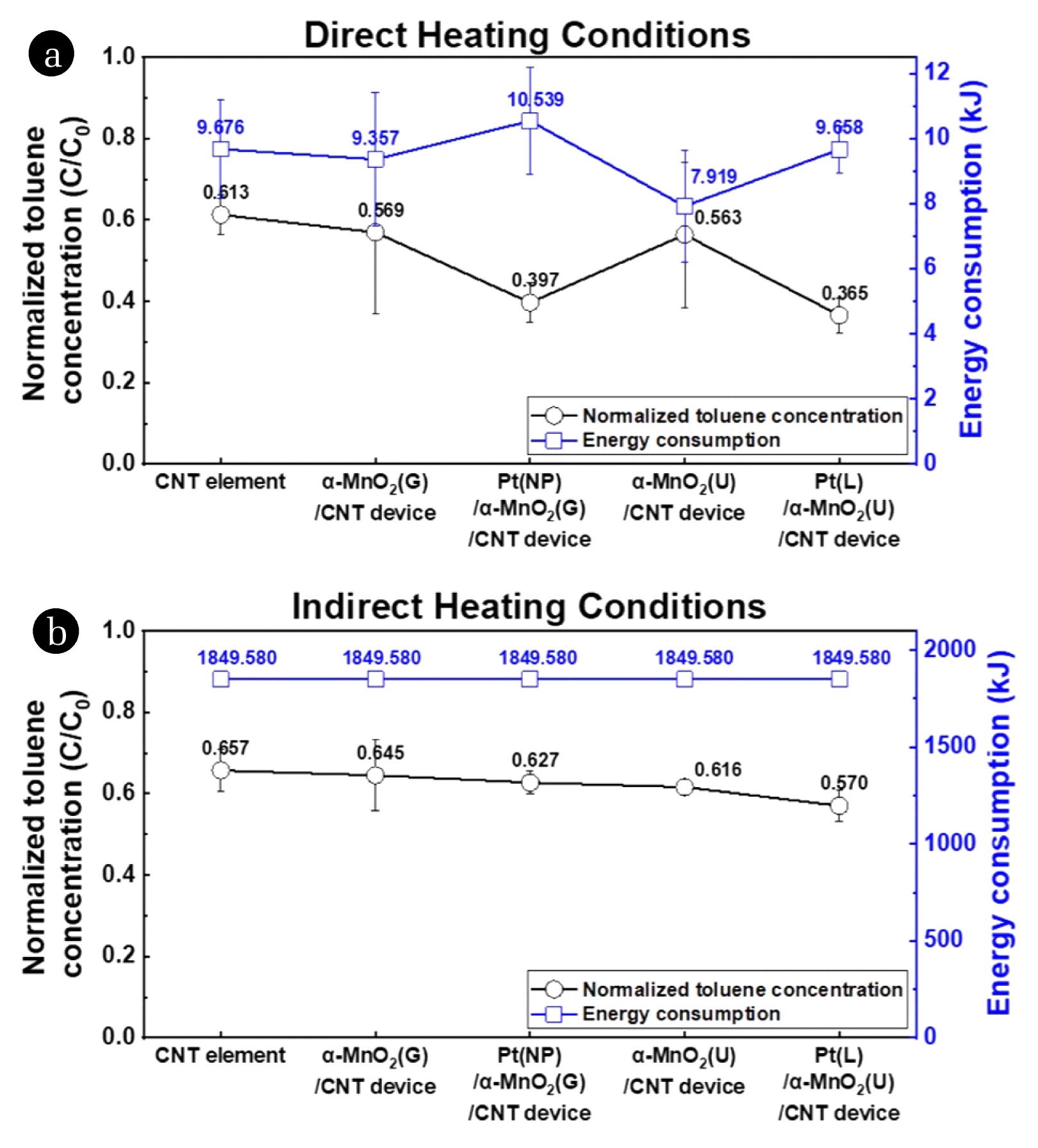
The toluene decomposition efficiency and energy consumption of each device were determined under direct and conventional indirect heating conditions. The reaction temperature of both processes was the same, i.e., 215 °C. The details of the temperature conditions and time–temperature curves of the direct and indirect heating processes are provided in the Supplementary Materials (Fig. S5). Fig. 6(a) and (b) show the normalized toluene concentrations after the catalyzed decomposition processes performed at 215 °C. The values of the normalized toluene concentrations of Fig. 6(a) and (b) are represented in Table S1.
First, under direct heating conditions, the thermal catalytic device featuring Pt(L)/α-MnO2(U)/CNT-coated glass-fiber textile achieves the lowest normalized toluene concentration (Fig. 6(a)) followed by the thermal catalytic device featuring Pt(NP)/α-MnO2 (G)/CNT-coated glass-fiber textile. Pt-decorated α-MnO2 nanostructures show higher toluene decomposition efficiency than pristine α-MnO2 nanostructures. Comparing previous studies, the catalytic activities of MnO2 structures combined with noble metal structures were higher than the pristine MnO2 structure as shown in Table S2. In general, MnO2 catalysts exhibit high catalytic efficiency when combined with Pt since the low-temperature catalytic activity of Pt is excellent. More specifically, noble-metal nanoparticles enhance the catalytic activity of metal oxides by promoting the migration of their oxygen vacancies[14,15].
Second, the thermal catalytic device featuring α-MnO2(U)/CNT-coated glass-fiber textile exhibit higher toluene decomposition efficiency than the thermal catalytic device featuring α-MnO2(G)/CNT-coated glass-fiber textile. The reason for the higher catalytic efficiency of the urchin-like α-MnO2 nanostructures is their comparatively higher specific surface area. As determined by FE-SEM, the urchin-like α-MnO2 nanostructures are nearly three-dimensional, in which one-dimensional nanowires are vertically arrayed, whereas the granular α-MnO2 nanostructures are two-dimensional structures that resemble a film. The urchin-MnO2 nanostructures exhibit higher roughness than granular-MnO2 nanostructures as shown in Fig. S3 and therefore have a higher specific surface area per equal-area (more details in Supplementary Materials). Furthermore, the XPS Mn 2p spectra of both α-MnO2(U)/CNT-coated and α-MnO2(G)/CNT-coated glass-fiber textile specimens display peaks at 642.0 eV corresponding to Mn4+ in the Mn 2p3/2 region; however, the Mn4+/Mn3+ associated with the former exceeds the Mn4+/Mn3+ associated with the latter (Table 1). Moreover, the O 1s spectrum of the α-MnO2(G)/CNT-coated glass-fiber textile specimen shows a major peak at 531.50 eV corresponding to Oads, whereas the O 1s spectrum of the α-MnO2(U)/CNT-coated glass-fiber textile specimen exhibits a major peak at 529.79 eV corresponding to Olatt and another major peak at 531.41 eV corresponding to Oads. According to Mo et al, the catalytic activity of MnO2 structures increases with increasing Mn4+ and Oads contents [15]. While the synthesized urchin-like α-MnO2 nanostructures have a higher relative Mn4+ content than the granular α-MnO2 nanostructures, their relative Oads content is lower. Thus, the urchin-like α-MnO2 nanostructures achieve higher toluene decomposition efficiency than the granular α-MnO2 nanostructures because both their relative Mn4+ content and specific surface area are higher.
Third, the toluene decomposition efficiencies of the devices under direct heating conditions exceed their decomposition efficiencies under indirect heating conditions (compare Fig. 6(a) and Fig. 6(b)). All the thermal catalytic devices including the CNT element perform better (in terms of toluene decomposition) under direct heating conditions than under indirect heating conditions (where the ambient air is heated). Under indirect heating conditions, the air containing the toluene gas in the quartz tube reaches the target temperature of 215 °C before the solid catalyst, which delays toluene decomposition. However, under direct heating conditions, the solid catalyst reaches the target temperature quickly due to the heat generated by the CNT element, reducing the delay in toluene decomposition associated with the indirect heating process. The indirect heating process is a convection process in which the temperature of the air is increased to increase the temperature of the catalyst, while the direct heating process is a conduction process that directly increases the temperature of the catalyst by increasing the temperature of the CNT element. Therefore, the conduction process, which increases only the air temperature near the catalyst, is more suitable for decomposing toluene at room temperature. The energy consumption of the indirect heating process is approximately 1849.580 kJ, while that of the direct heating process is 7.919–10.539 kJ. Therefore, our proposed thermal catalytic device demonstrates higher toluene decomposition efficiency and lower energy consumption under direct heating conditions than under conventional indirect heating conditions.
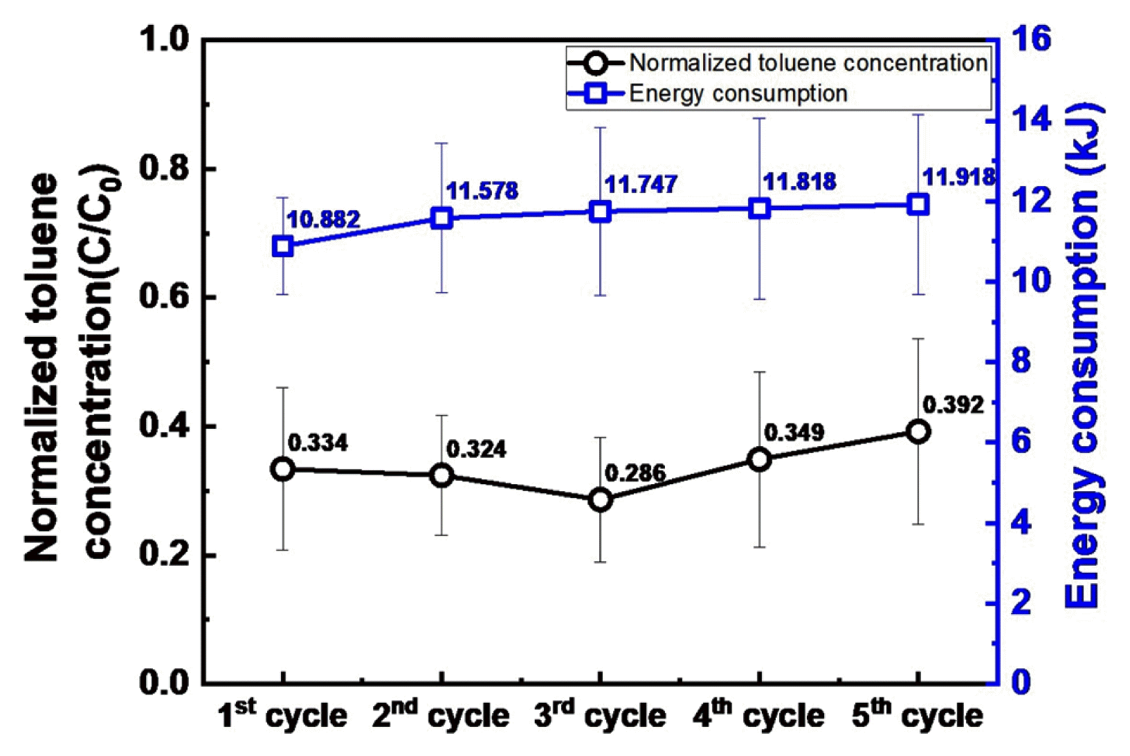
4.2. Repeatability Test
Because the constituent materials of the thermal catalytic device are heat-resistant, this device shows no deterioration in its catalytic and electrical properties even at an operating temperature of 215 °C. Fig. 7 presents the normalized toluene concentrations and associated energy consumption achieved by a Pt(L)/MnO2(U)/CNT device used in five successive toluene decomposition processes. The normalized toluene concentration and energy consumption achieved in the first cycle are 0.334 and 10.882 kJ, respectively; the corresponding values in subsequent cycles vary slightly, with a normalized toluene concentration and energy consumption of 0.392 and 11.918 kJ, respectively, achieved in the fifth cycle. The energy consumption decreases slightly as the thermal cycle is repeated because any remaining uncured binder in the CNT layer cures under the direct heating conditions. The toluene decomposition efficiency achieved in the fifth cycle is slightly higher; however, the toluene decomposition efficiencies of the cycles are generally fairly comparable. Once the binder in the CNT layer is fully cured, the catalytic efficiency and energy consumption of the thermal catalytic device are fairly stable. In addition, constituent materials of this thermal catalytic device show no structural deformation after the repeated cycle as shown in Fig. S6. This indicates that the thermal catalytic device is thermally and chemically stable and suitable for repeated/long-term use.
5. Conclusions
In this study, a thermal catalytic device was developed that exhibits enhanced catalytic activity toward the oxidation of VOCs under direct heating conditions, resulting in low energy consumption. The proposed thermal catalytic device was fabricated using a series of simple wet chemical synthesis processes. We investigated the effect of different α-MnO2 nanostructures, i.e., granular and urchin-like MnO2 nanostructures, on the performance of the thermal catalytic device. The urchin-like α-MnO2 nanostructures show higher catalytic activity than the granular α-MnO2 nanostructures owing to their higher specific surface area. The device featuring urchin-like α-MnO2 nanostructures that are coated in a thin layer of Pt shows particularly high catalytic activity because the thin layer of Pt, a noble metal, that is deposited on the urchin-like α-MnO2 nanostructures during a galvanic displacement reaction preserves the urchin-like shapes of the α-MnO2 nanostructures and their high specific surface area. The thermal catalytic device, operating under direct heating conditions, enables the rapid heating of the catalyst to its activation temperature, thereby achieving 1.71 times higher toluene decomposition efficiency and 191.51 times lower energy consumption than under conventional indirect heating. In addition, the thermal catalytic device, under the direct heating conditions, exhibits stable catalytic activity during repeated operation at high temperature. Owing to the enhanced toluene decomposition efficiency and low energy requirements of the proposed thermal catalytic device, it has significant potential for application at sites where VOCs are emitted at room temperature.