This is an Open Access article distributed under the terms of the Creative Commons Attribution Non-Commercial License (http://creativecommons.org/licenses/by-nc/3.0/) which permits unrestricted non-commercial use, distribution, and reproduction in any medium, provided the original work is properly cited.
Abstract
Membrane Bioreactors (MBR) have several advantages, but membrane fouling is a major disadvantage that prevents them from being widely used. Therefore, in the present study, the sponge was utilized as a pre-filter with coarse and fine pores in successive compartments before the membrane compartment and termed a “Hybrid-Membrane Bioreactor (H-MBR)”. In the present study, Conventional Membrane Bioreactor (C-MBR) and H-MBR were operated under similar operating conditions to evaluate the performance of H-MBR. The C-MBR experienced more frequent fouling within 60 days of operation, whereas in the H-MBR, the fouling was very low and gradual (i.e., 4.6 kPa at the end of 150 days of operation). Because of the low fouling, the need for cleaning was also eliminated for the stipulated operational period. The overall fouling rate of C-MBR and H-MBR was 5.83 kPa/d and 0.03 kPa/d, respectively. Both MBRs were good at organic pollutant removal. Because of the modification made in the present study, the H-MBR showed 14.66 times less cake layer resistance and 30 times less irreversible fouling resistance than the C-MBR. As a result, the H-MBR is effective in reducing both cake layer resistance and irreversible fouling resistance by retaining both cake-forming materials and irreversible foulants.
Membrane bioreactors (MBRs) are a combination of biological treatment and solid-liquid separation by a membrane [1]. Membrane bioreactors have higher effluent quality, lower hydraulic retention time, higher solids retention time, smaller footprint, ease in maintenance of high biomass concentration, and less sludge production. The effluent of MBR is also free of pathogens and microorganisms [2]. Despite several advantages offered by the MBRs, membrane fouling remains a major drawback, deterring their widespread application. Membrane fouling is the accumulation of feed water and mixed liquor constituents on the membrane surface and inside the membrane pores. The mechanism of fouling can be named cake layer formation, pore narrowing, and pore blocking. Among them, cake layer formation was found to be the most important contributor to membrane fouling [3]. Because of fouling, the reduction of membrane flux or increase of transmembrane pressure would occur under constant pressure mode or constant flux mode, respectively. Membrane fouling also causes a reduction in membrane life and increases the energy required for backwashing, making the system less efficient [4].
Various studies tried to mitigate membrane fouling by adopting various methods such as pre-treatment of feed, optimizing the operating conditions, surface modification of the membrane, and the addition of powdered activated carbon, granular activated carbon, and some other additives. Usually, wastewater contains suspended solids, microorganisms, organic pollutants, and nutrients that might contribute to membrane fouling. In previous studies, it was claimed that pre-treatment of the wastewater would help reduce membrane fouling. For the pre-treatment of wastewater, the attached growth process could be a suitable option due to its simple operation, use of inexpensive material, and high efficiency. Since the attached growth bioreactor has been approved for MBR pre-treatment, numerous studies have been done to integrate these two reactors into one hybrid system [5]. Freely suspended carriers have been used in MBRs to reduce membrane fouling. In previous studies by Lee et al. [6], Liu et al. [7], and Wang et al. [8], these carriers were put into a conventional membrane bioreactor (C-MBR). As the bioreactor had both suspended and attached biomass at the same time, a modified membrane bioreactor was made. Carriers can act as an immobilizing matrix or support for microorganisms and biofilm development. Carriers could also reduce the concentration of potential foulants such as Extracellular Polymeric Substances (EPS) and Soluble Microbial Products (SMP) [9]. In addition to passive immobilization (bio-film on surfaces), entrapment (cell trapping in the porous space of the carrier) would also occur while using carriers. These would be beneficial to reduce membrane fouling. According to Ngo et al. [10], a sponge can act as a mobile carrier, retain microorganisms, and minimize cake layer formation. Ngo et al. [11] claimed that because of the sponge’s high porosity, lightweight, and large specific surface area, it has demonstrated good performance. Previous studies by Guo et al. [12], Guo et al. [13], and Nguyen et al. [14] have concluded that the addition of a sponge with a volume fraction of 10–20% of the reactor’s volume resulted in effective nutrient removal as well as fouling reduction.
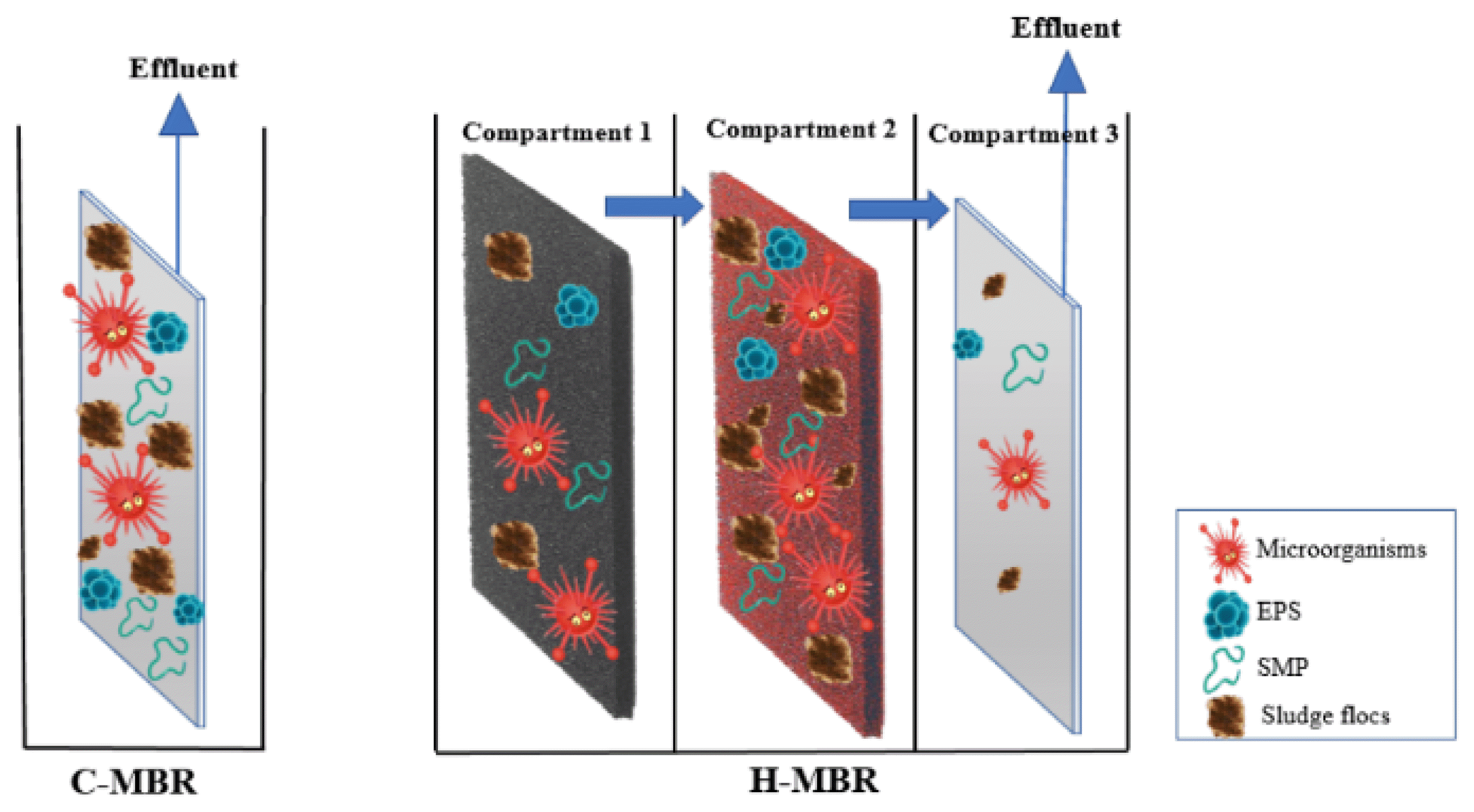
From the previously published work of Jamal Khan et al. [15], Nguyen et al. [16], and Zuthi et al. [17], it is clear that the addition of a sponge has effectively increased the biomass concentration in the reactor, enhanced the removal of organic pollutants, and slowed down the increase of transmembrane pressure (TMP). Hence, a higher flux can be maintained without frequent membrane cleaning. In all the previous studies, the sponge was added as a suspended media within the membrane compartment, and one of the mechanisms of fouling reduction was through scouring the membrane surface by suspending the sponge carrier. But Huang et al. [18] reported that the sponge carriers in suspension have broken up the sludge flocs because of the collision between sponges and sludge flocs and thus increased the membrane fouling over a period of time. To address this issue, sponges were used as fixed pre-filters in the current study. Also, previous studies have not yet focused on adding a sponge as a pre-filter (to avoid contact of sponges with membrane surfaces) or on the utilization of this pre-filter in subsequent compartments with different pore sizes. Therefore, in the present study, the sponge was utilized as a pre-filter with coarse and fine pores in successive compartments before the membrane compartment. The idea behind this configuration was to utilize biomass retention to have fewer biosolids in the membrane compartment in an attempt to reduce fouling. The MBR coupled with sponge pre-filters (coarse and fine) has been named hybrid MBR (H-MBR) in the present study. A conventional MBR (C-MBR) was operated under similar operating conditions to evaluate the performance of the H-MBR. The objectives of this study were (i) to evaluate the performance of H-MBR in treating synthetic wastewater, (ii) to compare the fouling phenomena of C-MBR and H-MBR in terms of TMP, and (iii) to study the effect of the addition of sponge as a pre-filter in successive compartments on sludge properties (MLSS, SVI, SMP, and EPS) and its relationship with fouling tendency.
Synthetic wastewater was used in this study throughout the operation to avoid any fluctuation in the feed concentration and to provide a continuous source of biodegradable organic pollutants such as sodium acetate, ammonium sulphate, and potassium dihydrogen orthophosphate. Synthetic wastewater has a COD value of 500 mg/L. The synthetic wastewater composition was adopted from the work of Mohan and Nagalakshmi [19] and is thus listed in Table S1. The COD:N:P ratio of synthetic wastewater was set to 100:10:1. To establish the stable performance of the reactor, seed sludge obtained from a domestic sewage treatment plant in Avaniyapuram (Tamilnadu), India, was acclimated for five weeks.
2.2. Sponge
Polyester-polyurethane sponges (PUS) with two different pore sizes were used as coarse-pore sponge filter and fine-pore sponge filter in H-MBR. In the present study, a coarse-pore sponge with a 1.69 mm pore diameter and a fine-pore sponge with a 0.51 mm pore diameter were utilised. Both PUS sponges have a density of 18 kg/m3. The cell count of the sponge was 15 and 50 pores per inch (PPI) for coarse and fine-pore sponge filters, respectively. It consisted of 15 cells/pores per 25.4 mm with a 1.69 mm diameter per pore for coarse-pore sponge filter and 50 cells/pores per 25.4 mm with a 0.51 mm diameter per pore for fine-pore sponge filter. The sponges with these sizes were selected because of their easy and wider availability in the market. The volume fraction of the sponge pre-filter in each compartment was approximately 10% of the reactor’s volume. The dimensions of the sponge filters were 30 cm × 50 cm × 2 cm in width, height, and thickness, respectively. The volume of sponge in each compartment was 3×10⁻³ m3 and the surface area was 0.15 m2. The sponges were acclimatized before being used in the H-MBR.
2.3. Reactor Setup
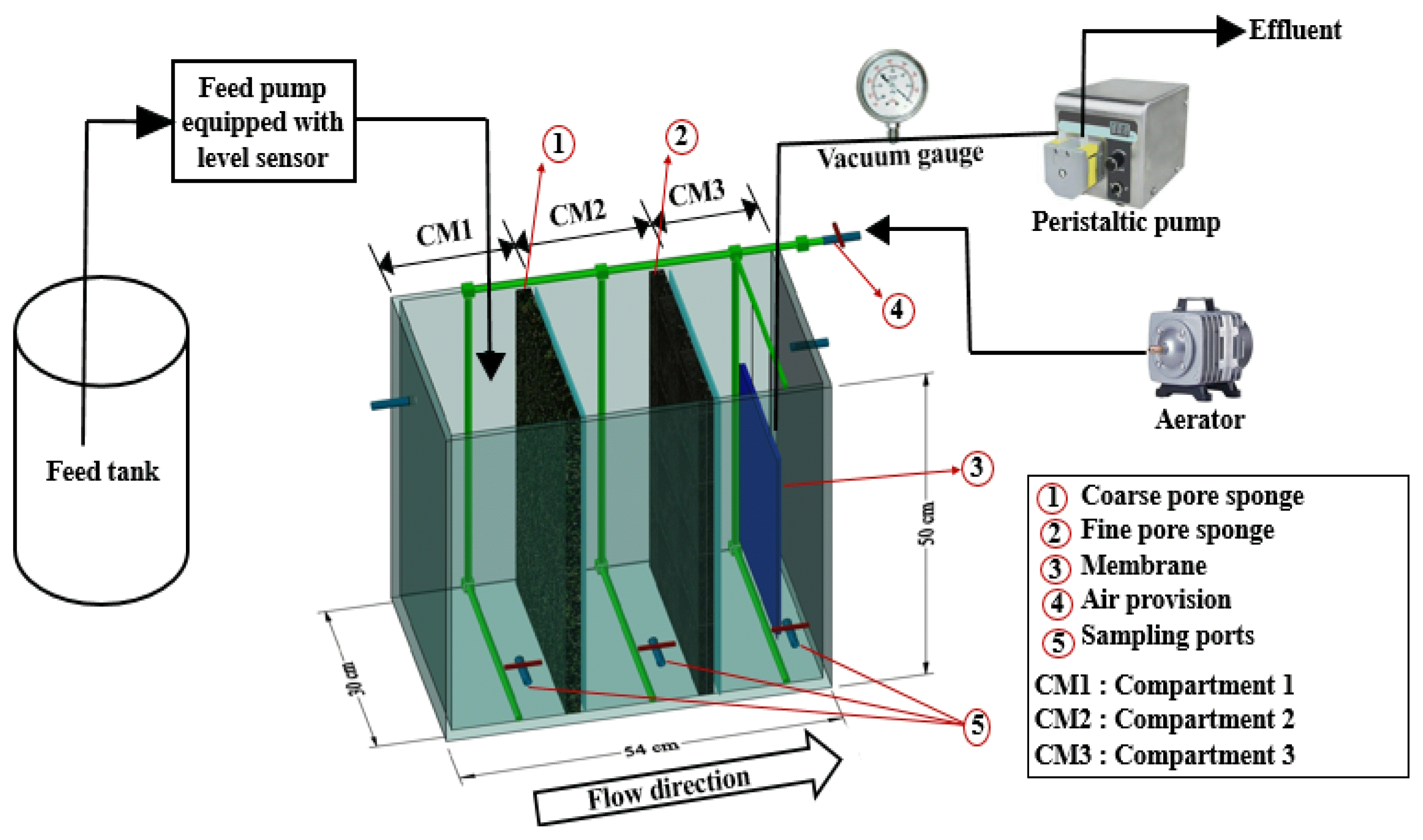
Fig. 1 shows the reactor configuration. Experimental runs for C-MBR and H-MBR were conducted consecutively and lasted for 60 and 150 days, respectively. A new flat-sheet PVDF microfiltration membrane (0.2 μm) with an area of 0.1 m2 (TECH INC. Chennai, India) was used in each run. A rectangular acrylic tank with 54 cm × 30 cm × 50 cm dimension and a working volume of 65 L was used. The total length (54 cm) of the reactor was divided into three compartments with solid acrylic plates, thus having an equal length for each compartment. The membrane was placed in the third compartment. In C-MBR, only the membrane compartment was used, whereas, in H-MBR, all three compartments were used, with the membrane in the last. In C-MBR, the feed entered the membrane compartment directly; in H-MBR, the feed entered the first compartment and, after passing through sponge filters, the feed reached the membrane compartment. In the first and second compartments, a coarse-pore sponge and a fine-pore sponge attached to a stainless-steel mesh screen are installed in front of each solid plate, respectively. There was a 5 mm gap between the mesh filter and the solid plate, and at the height of 42 cm from the bottom of each solid plate, the effluent ports were provided. The idea behind this setup was to let the wastewater pass through the coarse-pore sponge filter first and then be lifted to a height of 42 cm in the 5 mm gap and then discharged into the second compartment. As stated previously, the effluent from the first compartment was passed through a fine-pore sponge filter in the second compartment and then discharged into the membrane compartment. These configurations were meant to reduce the membrane’s susceptibility to fouling. In the membrane compartment, the membrane was positioned 5 cm above the air provision for both runs. The constant working volume of the reactor was maintained by an influent pump equipped with a level sensor. Compressed air was employed to maintain the bioreactor’s aerobic environment. At 19 cm from the bottom of each compartment, there was a port for taking samples. This was done near the middle of the working height of the reactor. Throughout this process, no sludge was wasted from the reactor, and the hydraulic retention time was 13 hours. A peristaltic pump (SP-Mini Pump, Shenchen Precision pump) was used to draw permeate through the submerged membrane at constant flux, and a vacuum gauge was used to monitor the suction pressure.
2.4. Analysis
Chemical oxygen demand (COD), Mixed Liquor Suspended Solids (MLSS) concentration, Mixed Liquor Volatile Suspended Solids (MLVSS), Sludge volume index (SVI), Ammonia Nitrogen (NH4-N), Total Kjeldahl Nitrogen (TKN), Nitrate Nitrogen (NO3-N), and Phosphate Phosphorus were determined according to standard methods [20]. The method for the extraction of Soluble Microbial Products (SMP), Loosely Bound Extracellular Polymeric Substances (LB-EPS), and Tightly Bound Extracellular Polymeric Substances (TB-EPS) were adapted from Banti et al. [21] and Zhang [22]. The amount of SMP, LB-EPS, and TB-EPS was taken as the sum of protein (PN) and polysaccharides (PS). The Phenol-Sulfuric acid method [23] was used to determine polysaccharides and the Lowry method [24] was used to determine the proteins. Relative hydrophobicity was measured according to the method by Ji et al. [25]. Flocculability and Surface Charge were determined as per the methods suggested by Wilén et al. [26].
Fourier transforms infrared (FTIR) spectroscopy, with the attenuated total reflectance (ATR) sampling technique, has been widely used to identify functional groups of sludge samples and to analyze the surface chemical composition and organic molecules adsorbed on a membrane. The attachment of polymeric substances on a coarse and fine-pore sponge after being used in H-MBR can be detected by FTIR. The wavenumber spectrum was determined over the range of 400 – 4000 cm−1.
2.5. Characterization of Membrane Resistance and Membrane Cleaning
Resistance-in-series model was used to find the resistances, namely intrinsic membrane (RM), reversible or cake (RC), irreversible pore blocking (RP), and the total resistance (RT) as per Eq. (1):
(1)
The total resistance can be evaluated from Eq. (2) by knowing the permeate flux and transmembrane pressure (TMP) data,
(2)
where J, ΔP, μ and RT are the permeate flux, trans-membrane pressure (TMP), permeate viscosity, and total resistance, respectively. Filtering tap water through the new membrane RM can be calculated. RT can be calculated at the end of the experiment by using Eq. (2). Similarly, RM + RP was calculated after removing the cake layer of the membrane and washing up the membrane with tap water. Subsequently, RC was calculated from Eq. (1).
The membrane was subjected to physical and chemical cleaning when the TMP reached 35 kPa. Physical cleaning was done to remove the cake layer by wiping the membrane surface with a soft sponge and rinsing the membrane surface with tap water until the adhering foulants were visually gone. After that, chemical cleaning was done by immersing the membrane in a 300 mg/L sodium hypochlorite (NaClO) solution for 2 hours and then rinsing it with tap water.
3. Results and Discussion
3.1. The Performance of C-MBR and H-MBR
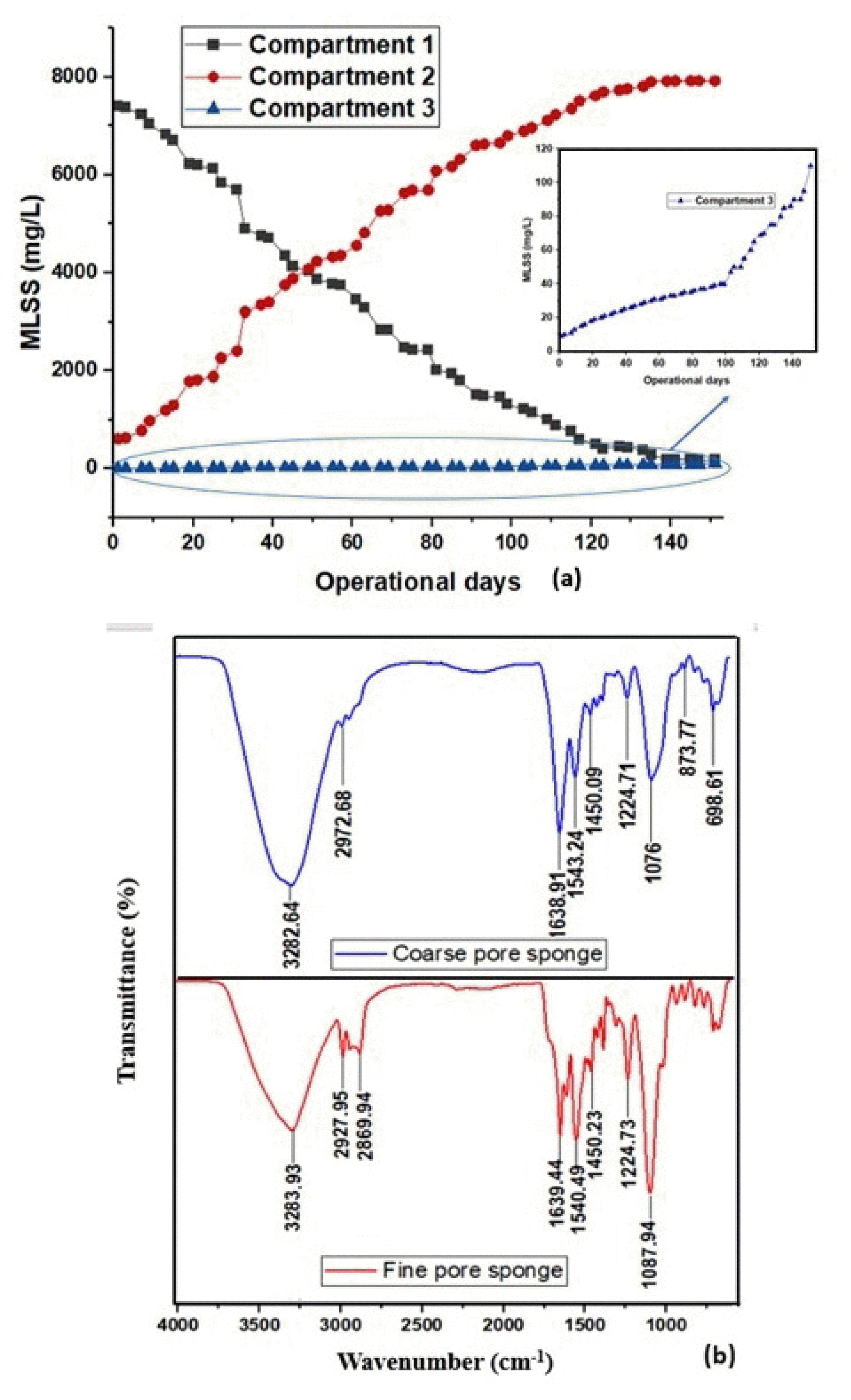
In C-MBR, all the MLSS were in the membrane compartment (8000±200 mg/L), whereas in H-MBR, MLSS was made to pass through sponge pre-filters, hence MLSS were distributed among the three compartments. Because of the pore size of the sponge pre-filters, the concentration of MLSS in each compartment varied. The coarse-pore sponge offered certain retention for biomass (i.e., up to 50% of total MLSS was in the 1st compartment for the first 49 days during 150 days of operation); hence, during the initial days, the MLSS concentration was higher in compartment 1 and then the MLSS started to move through the coarse-pore sponge. Because of that, the MLSS concentration in compartment 1 started to reduce. But the fine-pore sponge in compartment 2 has offered very good retention (i.e., the MLSS concentration was ≈10% during the initial days of operation and >90% after the 115th day of operation to the end), therefore the MLSS concentration has been increasing in compartment 2. Because of the retention of the fine-pore sponge, the solids reaching compartment 3 were also less. Hence, at the end of the operation (the 150th day), there was a maximum concentration of MLSS in compartment 2 and a very low concentration of MLSS in compartments 1 and 3. This fact was confirmed in Fig. 2 (a), where a pattern of MLSS concentration in compartments 1 and 2 showed decreasing and increasing trends, respectively. The intersection of the increasing and decreasing MLSS in compartments 2 and 1, respectively, occurred on the 49th day of operation. On the 49th day, compartments 1 and 2 had 50% of the total MLSS concentration in them. On that day, compartment 1 had a 46% decrease in concentration compared to the 1st day, and compartment 2 had an 85% increase in concentration compared to the 1st day. The fine-pore sponge has been retaining the maximum MLSS concentration for 2/3rd of the total operational days; still, it showed good retention till the end of the operation. Irrespective of MLSS concentration, the C-MBR and H-MBR were very good at organic pollutant removal, as the effluent COD concentration was found to be less than 10 mg/L in both cases. This might be because of the retention of biomass by the membrane and also because the easily biodegradable influent (sodium acetate) was used as the carbon source in this study. The ammonia nitrogen removal efficiency was also high (≥99%) in both MBRs, which was due to the retention of nitrifying bacteria by MBRs and infinite SRT. The nitrate-nitrogen concentrations in the effluents of C-MBR and H-MBR were 22.63±0.88 mg/L and 13.23±1.08 mg/L, respectively. The phosphorus removal was higher in H-MBR (75.80±1.70%) than in C-MBR (39.89±3.13%) which might be because of alternative exposure to anaerobic and aerobic zones in the interior and exterior of the sponges. The sponges used in this study could have provided an anaerobic condition because of their thickness (2 cm). Deng et al. [27] and Guo et al. [13] also reported increased phosphorus removal while using sponge cubes and reported that the removal was due to alternate exposure conditions around and inside sponge cubes.
FTIR analysis was used to provide more detailed information on the accumulation of biopolymers in the sponges after being used for the course of 150 days of operation. Fig. 2 (b) showed the FTIR spectra of coarse and fine-pore sponges. The peaks at 3283.93 cm−1 and 3282.64 cm−1 for fine-pore sponge and coarse sponge, respectively, are attributed to the stretching of the O-H bond in the hydroxyl functional group. The sharp peaks at 2927.95 cm−1 and 2972.88 cm−1 were due to C-H bonds [28]. The peaks at 1639.44 cm−1 and 1638.91 cm−1 were caused by the N–H bend and N–C=O stretch, which was indicative of the protein secondary structure [29]. The peaks at 1540.49 cm−1 and 1543.24 cm−1 were associated with the proteins’ amide groups; at 1450.23 cm−1 and 1450.09 cm−1 were possibly associated with the proteins’ aromatic phenolic groups [30]. The peaks at 1224.73 cm−1 and 1224.71 cm−1 were associated with the secondary amides of proteins (amide III) [31]. Also, the peaks at 1087.94 cm−1 and 1076 cm−1 were attributed to C-O bonds associated with polysaccharide or polysaccharide-like substances [29]. The peaks of a band <1000 cm−1 were observed in the fingerprint region, indicating humic substances due to aromatic compounds [32]. From the observations of FTIR, it was indicated that proteins and polysaccharides, which are the components of biopolymers, were found on both coarse and fine-pore sponges. Hence, the sponges not only have retained MLSS but also have provided a surface for the attachment of proteins and polysaccharides.
3.2. Membrane Fouling Behaviour and Filtration Resistances of C-MBR and H-MBR
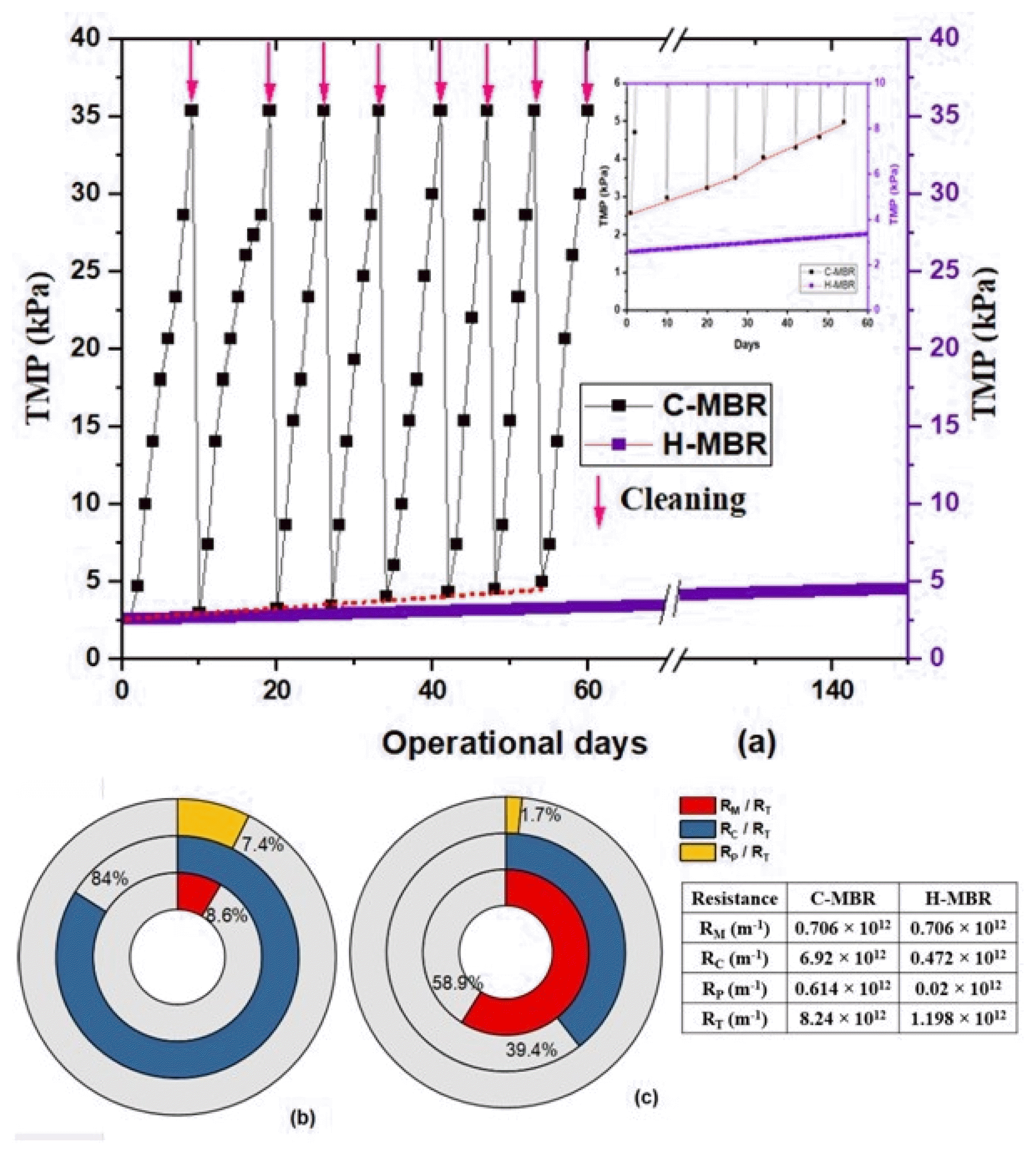
In this study, the operation was carried out under constant flux (15.38 LMH) mode, hence transmembrane pressure (TMP) was used as an indication for membrane fouling. In C-MBR, the operation was paused, and the membrane was removed from the reactor and subjected to cleaning whenever the TMP reached 35 kPa. From Fig. 3 (a), it can be seen that C-MBR experienced the most frequent membrane fouling, followed by cleaning (indicated by arrow marks). In Fig. 3 (a), as the irreversible fouling line of C-MBR was merged with the TMP line of H-MBR, an inset figure was provided. In that inset figure, a different scale was used for C-MBR and H-MBR to enhance the readability of the irreversible fouling line. Since the fouling and cleaning were repeated frequently, the operation was terminated after 60 days in C-MBR. The dotted line in Fig. 3 (a), indicated the occurrence of irreversible fouling in the C-MBR, and the inclination of the line progressed, which represented the increase in irreversible fouling after each cycle of operation. The cleaning has restored the performance of the membrane in C-MBR, as there was little difference between the TMP of initial membrane resistance and membrane resistance after each cleaning. The initial membrane resistance caused the initial TMP of 2.6 kPa. The maximum fouling rate of C-MBR was 5.83 kPa/d and occurred between 42 and 53 days of operation, which were the shortest operational days (6 days), whereas in H-MBR the fouling was very low and was slow and gradual. In other words, the H-MBR never experienced sudden TMP rise and frequent membrane fouling. Hence, H-MBR was operated on for 150 days without any cleaning, and the corresponding TMP at the end of the operation was 4.6 kPa. The fouling rate of H-MBR was 0.03 kPa/d, which was much lower than C-MBR. If the same fouling rate (0.03 kPa/d) prevailed continuously, the H-MBR could be operated for 2440 days (around 6.6 years) to reach the maximum TMP of 35 kPa. Nguyen et al. [5,16] reported a higher fouling rate of 0.12, 0.23, and 0.5 kPa/d in the sponge-submerged membrane bioreactor, in which the sponges were kept in suspension. But in the present study, sponges were kept as pre-filters. Hence, it could be inferred that the present configuration might have helped to reduce the fouling rate compared to previously published works on sponges in suspension. The work of Deng et al. [27] reported a fouling rate of 0.02 kPa/d for the flux of 10 LMH, which was less than the fouling rate of the present study. The increase in fouling rate from 0.02 kPa/d to 0.03 kPa/d in the current study could be offset by an increase in flux (15.38 LMH). Therefore, it can be stated that the modification made in the present study was helpful to reduce membrane fouling under the given flux conditions.
Fig. 3 (b) and (c) represented the percentage distribution of membrane, cake layer, and irreversible fouling resistances in total resistance in the C-MBR and H-MBR, respectively. The C-MBR and H-MBR had the same RM, but their distribution with total resistance varied significantly, such as by 8.6% and 58.9%, because of variation in the total resistance. The C-MBR had higher total resistance as it reached 35 kPa, whereas H-MBR had lower total resistance because its TMP at the end of the operation (150th day) was only 4.6 kPa. In C-MBR, resistance due to the cake layer contributed to 84% of total resistance with an RC of 6.92×10¹² m−1, whereas in H-MBR it was 39.4% of total resistance with an RC of 0.472×10¹² m−1. Higher cake layer resistance in C-MBR might be due to the higher MLSS concentration. But in H-MBR, the MLSS was retained by the sponge pre-filters, and hence the concentration of MLSS in the membrane compartment was less (as discussed in Section 3.1), which might have led to lower cake layer resistance (nearly 14.66 times lower than C-MBR). This suggested that controlling cake layer resistance could reduce membrane fouling to a greater extent. The irreversible fouling resistance was 0.614×10¹² m−1 and 0.02×10¹² m−1 for C-MBR and H-MBR, respectively. Accumulation of polymeric substances and compaction of the cake layer on the membrane surface are known to contribute to the irreversible fouling of the membrane [33]. There was a high possibility of direct accumulation of polymeric substances on the membrane surface in C-MBR, which could have resulted in higher irreversible fouling resistance. But in H-MBR, the sponges were provided before the membrane compartment, and they retained polymeric substances, which were confirmed from the FTIR results (as discussed in Section 3.1). Based on the calculation, it was found that H-MBR had nearly 30 times less irreversible fouling resistance than C-MBR. This indicated that the H-MBR used in this study was beneficial to reduce membrane fouling in terms of both cake layer resistance and irreversible fouling resistance, and thereby total resistance. Furthermore, the need for cleaning the membrane was also eliminated for this configuration within the stipulated operational period (150 days).
3.3. Influence of Microbial Products (SMP, LB-EPS, & TB-EPS) on Membrane Fouling
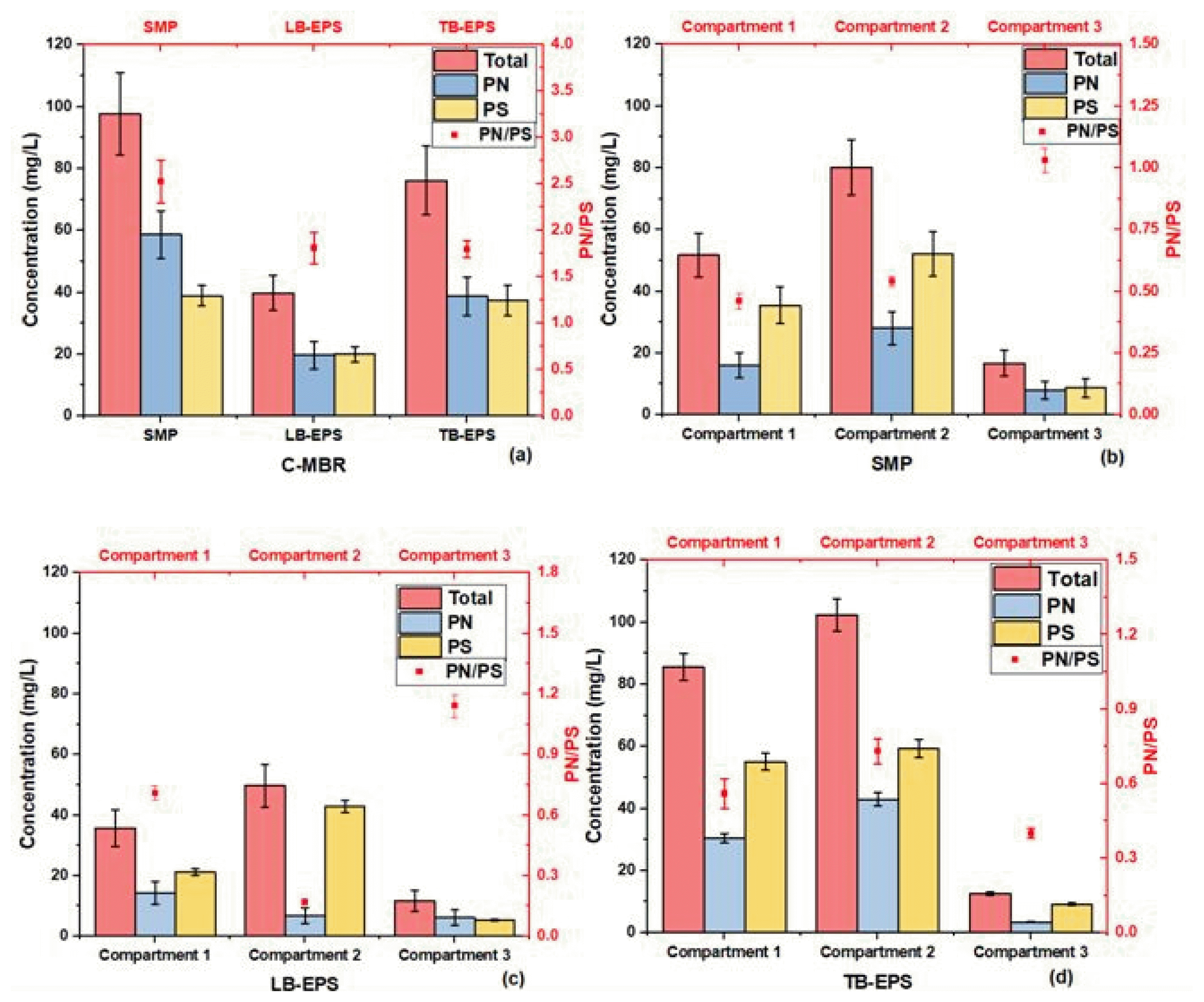
SMP and EPS are microorganism secretions with a high molecular weight and a gel-like, three-dimensional structure. EPS and active cell decay products form SMP, which are the prime causes of membrane fouling [34]. EPS are cell-bound, dynamic double-layer structures that can be classified as loosely bound EPS (LB-EPS) and tightly bound EPS (TB-EPS) [21]. Fig. 4 (a) showed the SMP, LB-EPS, and TB-EPS’s total, protein and polysaccharide concentrations, and PN/PS ratio of the C-MBR. From Fig. 4 (a), it can be noted that the SMP concentration was higher than LB-EPS and TB-EPS. This might be due to the hydrolysis of bound EPS, which would have increased the concentration of SMP. When looking into the concentration of SMP, it can be noted from Fig. 4 (a) and (b) that C-MBR had a higher SMP concentration (97.62±13.31 mg/L) than H-MBR’s three compartments (51.68± 1.27, 80.18±1.27 and 16.73±0.56 mg/L in compartments 1, 2, and 3, respectively). In H-MBR, SMP concentration was higher in compartment 2 compared to compartment 1, which might be because of the higher concentration of MLSS in compartment 2 than in compartment 1. But there was a noticeable minimum SMP in compartment 3, which was nearly 3 times and 4.7 times less than compartments 1 and 2, respectively. The low SMP concentration in the 3rd compartment could be attributed to the very low MLSS concentration and the high biomass retention of the fine-pore sponge. SMP could colonize on the membrane surface and facilitate the further adhesion of sludge flocs that lead to membrane fouling [35]. This might be the reason for frequent fouling in C-MBR and less fouling in H-MBR. Also, the studies by Lee et al. [36] and Shen et al. [34] mentioned that SMP could cause irreversible fouling by blocking the membrane pores. In this study, C-MBR had nearly 5.8 times higher SMP than in H-MBR’s compartment 3 and the irreversible fouling resistances of C-MBR and H-MBR were 0.614×10¹² m−1 and 0.02×10¹² m−1, respectively. PN/PS of SMP in C-MBR was 2.53±0.23 and in H-MBR’s 1st, 2nd and 3rd compartments were 0.46±0.03, 0.54±0.02 and 1.03±0.05, respectively.
C-MBR had a higher concentration of PN than PS for SMP and TB-EPS (Fig. 4 (a)). In C-MBR, all of the MLSS was kept in a single compartment, so the microorganisms could have fed on polysaccharides. Therefore, PN was higher than PS in C-MBR. Because of the stickiness of PN, a higher concentration of PN in the mixed liquor solution would promote cake layer formation on the membrane. Hence, C-MBR had higher cake layer resistance (6.92×10¹² m−1) than H-MBR. But H-MBR had a higher PS concentration than PN concentration in SMP and TB-EPS in all three compartments. Consumption of protein by the microorganisms could be the reason for the low PN concentration. Rafiei et al. [9] reported that macromolecules like proteins (that are already present in the system) can be consumed by microbial culture after the substrate is effectively removed from the bioreactor. Also, PN are hydrophobic in nature, so they repel water and attach to the sponge filters, which might have also resulted in a low PN in the mixed liquor of H-MBR. But in compartment 3, the PS concentration was nearly the same as the PN concentration for LB-EPS. Lin et al. [37], Meng et al. [38], and Teng et al. [39] mentioned that flocculability, settleability, and filterability are influenced by LB-EPS rather than TB-EPS. That means the components (PN and PS) of LB-EPS contributed more to influencing the sludge properties than TB-EPS. The PN of LB-EPS in the membrane compartment might have readily attached to the membrane surface to form a cake layer on it, and little PS was consumed by microorganisms through endogenous metabolism. Hence, an equal concentration of PN and PS might have been encountered. The PN/PS ratio varied in Fig. 4 (a), (b), (c), and (d) based on the concentration of PN and PS. Because the PN concentration was higher in C-MBR and their PN/PS ratio was also higher (1.80 to 2.53), whereas in H-MBR PN was lower than PS, the corresponding PN/PS was lower (0.40 to 1.03).
LB-EPS in C-MBR, H-MBR’s 1st, 2nd, and 3rd compartments were 39.83±5.71, 35.63±1.02, 49.75±1.08, and 11.74±0.26 mg/L respectively. Khan et al. [35] reported that LB-EPS was well correlated with membrane fouling. Because LB-EPS contain high molecular weight (MW) substances and tend to form a gel layer with a higher cross-linking level [39]. In the present study, the C-MBR had a nearly threefold higher LB-EPS than the H-MBR’s 3rd compartment. This could be the reason that the C-MBR has experienced more frequent fouling than H-MBR. Because the higher concentration of LB-EPS in C-MBR has formed a gel-like layer on the membrane surface, this would have facilitated the further deposition of sludge flocs on them. The PN/PS ratio of LB-EPS in C-MBR and H-MBR’s 1st, 2nd, and 3rd compartments were 1.81±0.17, 0.71±0.04, 0.17±0.01, and 1.14±0.04, respectively. When the PN/PS of bound EPS is greater, protein predominance is possible, which could be due to the fact that cellular structures and enzymes are mostly proteins in nature [15].
In Fig. 4 (a), (c), and (d), the TB-EPS was around twice as high as the LB-EPS for the C-MBR and H-MBR’s 1st and 2nd compartments, except for the 3rd compartment. LB-EPS are more easily biodegradable than TB-EPS, and hence the LB-EPS in C-MBR and H-MBR’s 1st and 2nd compartments might have been biodegraded by the microorganisms because they had a higher MLSS concentration. But in the 3rd compartment of H-MBR, the MLSS concentration was low, and hence the biodegradation of LB-EPS was also low; therefore, the concentrations of LB-EPS and TB-EPS were nearly equal. TB-EPS in C-MBR and H-MBR’s 1st, 2nd, and 3rd compartments were 76.15±11.09, 85.52±4.91, 102.28±3.53, and 12.66±0.46 mg/L, respectively. EPSs are generally known to be the reason for the formation of a cake layer on the membrane surface (reversible fouling) because TB-EPSs are very adhesive in nature [40,41]. In the present study, C-MBR had a TB-EPS concentration around 6 times higher than H-MBR’s 3rd compartment. Hence, this might be the reason for the increased cake layer formation and frequent fouling associated with higher cake layer resistance in C-MBR. The PN/PS ratios of the C-MBR and H-MBR’s 1st, 2nd, and 3rd compartments were 1.80±0.09, 0.56±0.06, 0.73±0.05, and 0.40±0.02, respectively. It has already been reported that a lower PN/PS ratio of the EPS resulted in a lower fouling propensity [42]. Likewise, in this study, the PN/PS ratio of H-MBR was lower than C-MBR’s, and it experienced much lower fouling than C-MBR.
From the above discussions, it can be inferred that the C-MBR had frequent fouling and higher cake layer resistance due to increased concentrations of PN and EPS (LB-EPS and TB-EPS) than the H-MBR. SMP might have caused the increased irreversible fouling resistance in C-MBR. Hence, the sponge pre-filters effectively reduced the concentration of polymeric substances and thereby reduced fouling intensity in H-MBR.
3.4. Relationship Between Components of Microbial Products and Sludge Properties
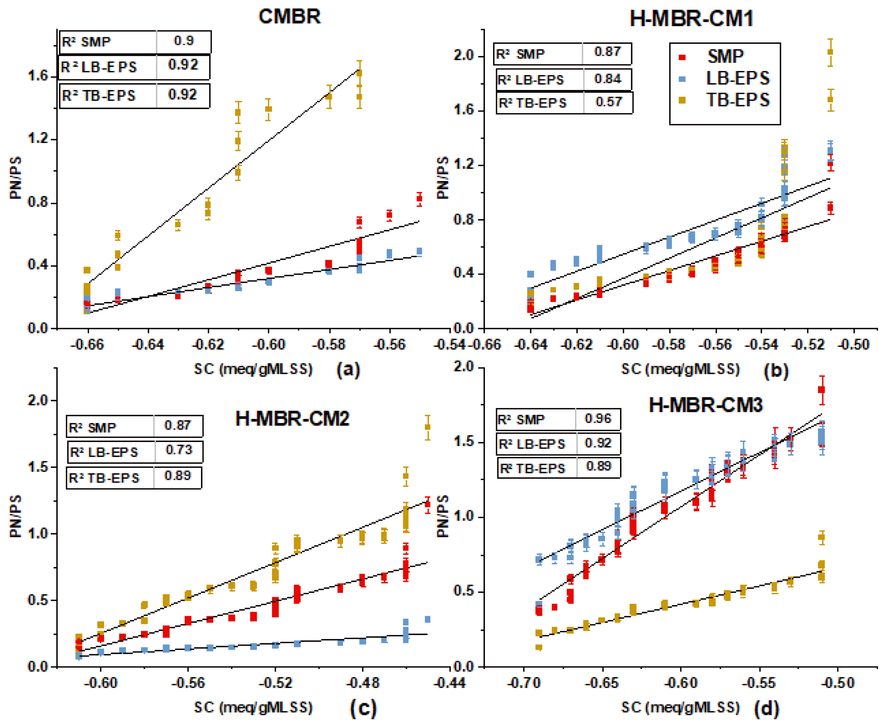
Surface charge, relative hydrophobicity, and flocculability are known to be affected by the PN and PS of polymeric substances. The SC for the C-MBR and H-MBR’s 1st, 2nd, and 3rd compartments were −0.47, −0.57, −0.53, and −0.61 meq/gMLSS, respectively. C-MBR had a higher PN concentration and hence a higher surface charge. Because PN carries a positive charge, it tends to neutralize negatively charged particles and thereby increase the SC. The amino groups of proteins are positive, which can neutralize the negative charges of carboxyl and phosphate groups, thereby increasing the SC. In H-MBR, the SC was higher in compartment 2, followed by compartments 1 and 3, which were in line with the PN concentrations of SMP and LB-EPS. From Fig. 5 (a), it can be seen that in C-MBR there was a very good correlation between SC and PN/PS of SMP, LB-EPS, and TB-EPS with R2 values of 0.9, 0.92, and 0.92, respectively. From Fig. 5 (b), (c), and (d), it can be noted that there was a very good correlation between SC and PN/PS of SMP, LB-EPS, and TB-EPS in compartments 2 and 3, and slightly less correlation for TB-EPS in compartment 1. This might be due to the overall PN/PS of TB-EPS, as the PN/PS of TB-EPS in compartment 1 (0.46±0.03) was less than that in compartment 2 (0.71±0.04) and compartment 3 (0.56±0.06). Even though the SC in the 3rd compartment was less, their correlation with the PN/PS of SMP, LB-EPS, and TB-EPS was very good. This means that the ratio of PN/PS contributes more to SC rather than the concentration of PN and PS. Although the PN and PS concentrations were lower in compartment 3, it still showed a very good correlation with SC and PN/PS. According to Zhang et al. [4], the increased PN/PS of LB-EPS increased SC. The present study followed the same trend by observing increased PN/PS of SMP and LB-EPS in C-MBR (2.53±0.23 & 1.81±0.17) and H-MBR’s 3rd compartment (1.03±0.05 & 1.14±0.04) and this correlated well with SC. The PN/PS of SMP and LB-EPS in compartment 1 (0.46±0.03 & 0.71±0.04) and compartment 2 (0.54±0.02 & 0.17±0.01) was less, and hence their correlation with SC was less (in Fig. 5 (b) and (c)).
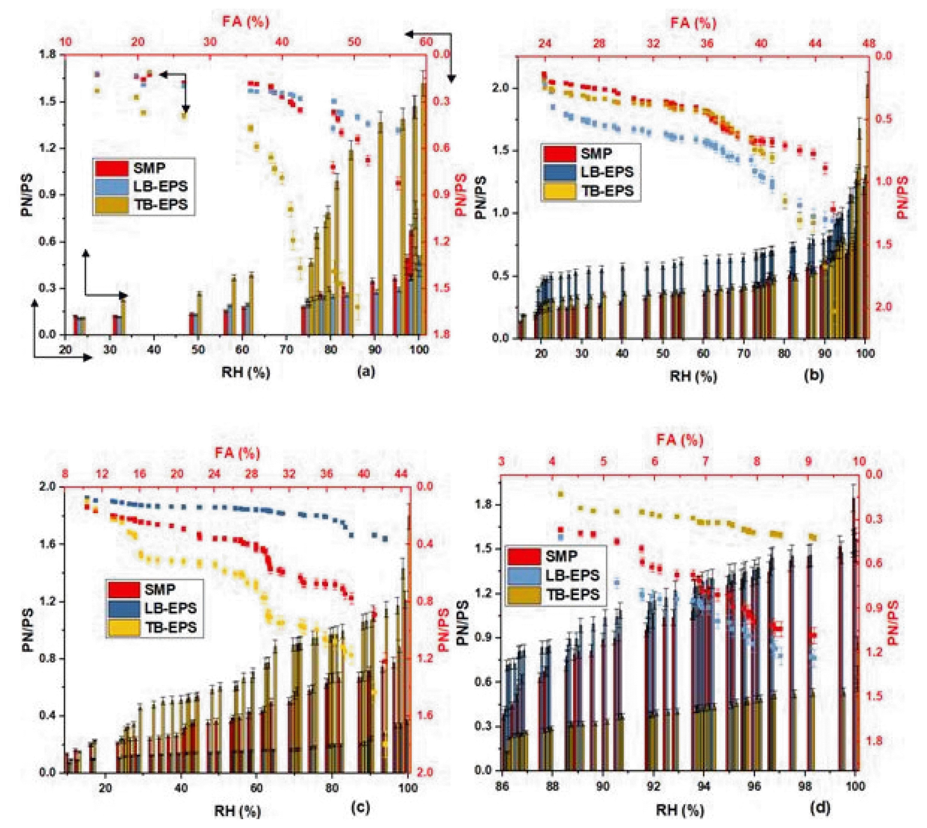
The relationship between PN/PS of SMP, LB-EPS, and TB-EPS with relative hydrophobicity and flocculability in C-MBR and H-MBR’s 1st, 2nd, and 3rd compartments were shown in Fig. 6 (a), (b), (c) and (d), respectively and their R2 values were mentioned in Table 1. Lee et al. [36] reported that a higher SC would increase the relative hydrophobicity and thereby increase flocculability, which would produce larger flocs through the adhesion of flocs with one another. From Table 1, it can be seen that C-MBR had a good correlation between RH and PN/PS of SMP, LB-EPS, and TB-EPS, as well as between FA and PN/PS of SMP, LB-EPS, and TB-EPS. The H-MBR also had a very good correlation between RH and PN/PS of SMP, LB-EPS, and between FA and PN/PS of SMP, LB-EPS, in all three compartments except for TB-EPS’s PN/PS with RH and FA in compartment 1. The poor correlation (R2=0.48) in compartment 1 might be due to changes in the environmental conditions of biomass in that compartment. The biomass’s living conditions may have changed because the MLSS was initially higher in the 1st compartment but later decreased, which would have had an impact on the biomass’s flocculability and relative hydrophobicity. Also, Desmond et al. [43] reported that an increased PN/PS of LB-EPS inhibited the attachment of bacteria and weakened the sludge matrix, and in the present study too, in compartment 1, the PN/PS of LB-EPS was higher than that of TB-EPS and SMP (reported in Section 3.3). Hence the LB-EPS might have affected the flocculability and relative hydrophobicity; therefore, there was a poor correlation between RH and TB-EPS, and between FA and TB-EPS in compartment 1. The average RH in C-MBR and H-MBR’s 1st, 2nd, and 3rd compartments were 81.20±4.56, 62.76±4.37, 56.91±3.84, and 92.55±0.65%, respectively. Zhang et al. [4] reported an increased relative hydrophobicity with an increase in PN/PS of LB-EPS. In the present study, the PN/PS of LB-EPS in C-MBR and H-MBR’s 1st, 2nd, and 3rd compartments were 1.81±0.17, 0.71±0.04, 0.17±0.01, and 1.14±0.04, respectively. The PN/PS of LB-EPS was greater than 1 for C-MBR and H-MBR’s 3rd compartment and experienced higher relative hydrophobicity. The average FA in C-MBR and H-MBR’s 1st, 2nd, and 3rd compartments were 38.98±2.23%, 34.01±0.92, 26.34±1.30, and 9.21±0.44%, respectively. The flocculability in compartment 3 was lower, which means there were dispersed flocs that could affect the filterability and cause membrane fouling. This might be the reason for the membrane fouling in H-MBR (4.6 kPa at the end of the 150th day) even with a low MLSS concentration.
The SVI of the C-MBR and H-MBR’s 3rd compartment was below 100 ml/g during the entire period of operation. Even though the C-MBR had good settling sludge, it experienced the most frequent fouling. The PN concentration in the mixed liquor might have caused the sludge to stick to the membrane surface and lead to fouling. The polymeric substances also played an important role in the membrane fouling of C-MBR. In H-MBR, the MLSS concentration was lower in the membrane compartment; hence, the fouling was also lower.
3.5. Statistical Analysis
To statistically signify the difference between the C-MBR and H-MBR in terms of membrane fouling and the PN/PS ratio of polymeric substances (SMP, LB-EPS, and TB-EPS), a one-way analysis of variance (one-way ANOVA) was performed at a 95% confidence level. The difference is said to significantly differ if the F value is higher than the F critical value; otherwise, there won’t be a significant difference. The TMP of C-MBR and H-MBR significantly differed because of the introduction of the sponge pre-filters before the membrane compartment. This proved that the H-MBR configuration made in this study was helpful to reduce the fouling significantly. From the above discussion of previous sections (sections 3.3 and 3.4), it was known that the PN/PS are more important than their concentration, and hence the PN/PS of SMP, LB-EPS, and TB-EPS were only analyzed for further statistical analysis. The PN/PS ratios of SMP, LB-EPS, and TB-EPS were checked for a significant difference among the three compartments of H-MBR. There was a significant difference between the three compartments because of the sponge pre-filters. Since there was a significant difference between the three compartments of the H-MBR, the C-MBR and the H-MBR’s 3rd compartment were compared. For the comparison with C-MBR, the 3rd compartment of H-MBR was only chosen because the membrane was in the 3rd compartment. The difference was significant for the PN/PS of the C-MBR and the H-MBR’s 3rd compartment. Since the difference was significant, it was clear that the sponge pre-filters have also helped to reduce the polymeric substances in H-MBR.
3.6. Mechanism of Fouling Control
MLSS was the major cake-forming material in C-MBR. Since the MLSS concentration was high, most of the biomass was directly attached to the membrane surface (as depicted in Fig. S1 (a)) and caused the membrane to reach the maximum TMP of 35 kPa most often. Whereas in the H-MBR sponge pre-filters (coarse and fine-pore) were introduced before the membrane compartment to facilitate the retention of MLSS. The percentage distribution of MLSS among the three compartments was due to the retention of each sponge filter, which was discussed in Section 3.1 and pictured in Fig. 2 (a). The sponge pre-filters reduced the concentration of MLSS in the membrane compartment, which in turn reduced membrane fouling due to cake formation (Fig. S1 (b)). Polymeric substances (SMP, LB-EPS, and TB-EPS) and their constituents (proteins and polysaccharides) also contributed to membrane fouling to a greater extent in C-MBR. A high concentration of protein contributed more to the cake layer formation because of their stickiness on the surface of the membrane, and SMP contributed to the irreversible fouling. Hence, the sponge pre-filters have retained them and thereby reduced their concentration in the membrane compartment. Most of the PN was attached to the sponge filters, which was confirmed by the FTIR studies. As a result, the modification made in the present study prevented the membrane from being attacked by both cake-forming materials and irreversible foulants.
3.7. Cost Analysis of C-MBR and H-MBR
For the purpose of cost analysis, it was assumed to construct a wastewater treatment plant of C-MBR and H-MBR to treat 1000 m3/day of wastewater for the design period of 40 years. For the cost analysis of C-MBR and H-MBR, the following assumptions and data were used: (a) capital construction cost for membrane tank is 1000–6000 euro (or) 1113–6678 $ for 1 m3/day [44] and for the cost analysis, an average value of 3896 $ for 1 m3/day was used; (b) membrane cost is 75–150 euro/m2 (or) 84–167 $/m2 [44] and 126 $/m2 was used; (c) cost of chemical cleaning is 24,100 $/year [45]; (d) operating cost is 0.24–0.25 euro/m3 (or) 0.27–0.28 $/m3 [44]; (e) energy consumption for MBR is 0.26–0.44 kWh/m3 [46] and for analysis, 0.35 kWh/m3 was used; (f) electricity cost was 0.096 $/kWh [45]; and (g) membrane replacement period is 8 years.
By using the above-mentioned data, the cost analysis for C-MBR was made as follows: (i) capital construction cost for 1000 m3/day = 38,96,000 $ (i.e., 3896 $ × 1000 m3/day); (ii) area of membrane required to treat 1000 m3/day wastewater with 15.38 LMH flux was 2778 m2 (i.e., (1000 m3/day) / (0.36 m3/day/m2)), and the cost incurred for the purchase of membrane was 17,50,140 $ (i.e., 126 × 2778 × 40/8) with a replacement period of 8 years; (iii) cost required for chemical cleaning was 9,64,000 $ (i.e., 24100 $ × 40); (iv) operating cost for 1000 m3/day was 280 $ (i.e., 0.28 × 1000); (v) energy consumption for membrane tank was 51,10,000 kWh (i.e., 0.35 kWh/m3 × 1000 × 365 × 40) for the design period of 40 years and the corresponding cost incurred for electricity was 4,90,560 $ (i.e., 51,10,000 kWh × 0.096 $/kWh); and (vi) The total cost of 71,00,980 $ is the summation of the costs incurred for the construction, membrane purchase, chemical cleaning, operation, and electricity.
The cost analysis for H-MBR was conducted similarly to C-MBR. In H-MBR, two sponge pre-filter tanks were provided with the membrane compartment, whereas in C-MBR, only the membrane compartment was used. Therefore, with the exception of chemical cleaning costs and membrane replacement costs, the cost analysis of the C-MBR discussed above can be applied to the membrane compartment of the H-MBR. Because it was expected that H-MBR would require 2440 days (6.6 years) to reach a maximum TMP of 35 kPa. As a result, it is expected that neither chemical cleaning nor membrane replacement will be necessary during the design period (40 years). For the cost analysis of H-MBR, the following assumptions were made: (a) the cost of both coarse and fine-pore sponges is 10% of the membrane cost; (b) the sponge replacement period is 2 years; (c) the aeration tank design criteria were used for the cost analysis of the sponge pre-filter tanks; (d) the capital construction cost of the aeration tank was 1,03,07,340 rubles (or) 1,28,120 $ [44]; and (e) the energy consumption for the aeration tank was 0.18–0.8 kWh/m3 [47]. As done for C-MBR, the cost analysis for H-MBR was also made in the same manner, and their costs are represented in Table 2. By comparison with C-MBR, the economic benefit gained with the adaptation of H-MBR was 12,83,620 $ for 1000 m3/d of flow rate with a design period of 40 years.
4. Conclusions
In this study, the conventional membrane bioreactor experienced frequent membrane fouling, with the cake layer as the dominant one. To overcome cake layer resistance, sponges with 1.69 mm and 0.51 mm diameters were used as coarse and fine-pore pre-filters before the membrane compartment.
The result of the present study provided valuable insight into different aspects of mitigating fouling on the membrane. Having mitigated fouling on the membrane, further research could be carried out on the economic aspect of the proposed configuration and compare it with the existing one.
As a maximum TMP of 35 kPa is expected to be attained in around 6.6 years, it is concluded that this configuration (H-MBR) provided ease of operation with less maintenance.
Hence in this study, the modification made by introducing sponges as pre-filters helped reduce total membrane resistance and its components, such as resistance due to the cake layer and irreversible fouling. As a consequence of that, there was no need for the cleaning of the membrane during the stipulated operational period of 150 days in H-MBR. This confirmed that the prevention of membrane surfaces from cake-forming materials (especially MLSS) could reduce membrane fouling to a greater extent.
The authors would like to thank the support of Alagappa Chettiar Government College of Engineering and Technology, Karaikudi, Tamilnadu, for providing lab facilities, and Avaniyapuram Sewage Treatment Plant, Tamilnadu, for providing sludge to carry out the experiments.
Notes
Conflict-of-Interest
The authors declare that they have no conflict of interest.
Author contributions
S.M. (Associate Professor in Civil Engineering) performed the conceptualization, methodology, investigation, and supervision; S.N. (PhD Scholar) performed conceptualization, visualization, original draft preparation, and editing.
Nomenclature
Symbol Definition
RC
Reversible or cake resistance
RM
Membrane resistance
RP
Irreversible (or) pore-blocking resistance
RT
Total resistance
J
Permeate flux
ΔP
Trans-membrane pressure
μ
Permeate viscosity
Reference
1. Hasan SW, Elektorowicz M, Oleszkiewicz JA. Correlations between trans-membrane pressure (TMP) and sludge properties in submerged membrane electro-bioreactor (SMEBR) and conventional membrane bioreactor (MBR). Bioresour. Technol. 2012;120:199–205.
https://doi.org/10.1016/j.biortech.2012.06.043
2. Liu Y, Liu Z, Zhang A, Chen Y, Wang X. The role of EPS concentration on membrane fouling control: Comparison analysis of hybrid membrane bioreactor and conventional membrane bioreactor. Desalination. 2012;305:38–43.
https://doi.org/10.1016/j.desal.2012.08.013
3. Jin L, Ong SL, Ng HY. Fouling control mechanism by suspended biofilm carriers addition in submerged ceramic membrane bioreactors. J. Membr. Sci. 2013;427:250–258.
https://doi.org/10.1016/j.memsci.2012.09.016
4. Zhang H, Fan X, Wang B, Song L. Calcium ion on membrane fouling reduction and bioflocculation promotion in membrane bioreactor at high salt shock. Bioresour. Technol. 2016;200:535–540.
https://doi.org/10.1016/j.biortech.2015.10.080
5. Nguyen TT, Ngo HH, Guo W, Li J, Listowski A. Effects of sludge concentrations and different sponge configurations on the performance of a sponge-submerged membrane bioreactor. Appl. Biochem. Biotechnol. 2012;167:1678–1687.
https://doi.org/10.1007/s12010-012-9579-x
6. Lee J, Ahn WY, Lee CH. Comparison of the filtration characteristics between attached and suspended growth microorganisms in submerged membrane bioreactor. Water Res. 2001;35:2435–2445.
https://doi.org/10.1016/S0043-1354(00)00524-8
7. Liu Q, Wang XC, Liu Y, Yuan H, Du Y. Performance of a hybrid membrane bioreactor in municipal wastewater treatment. Desalination. 2010;258:143–147.
https://doi.org/10.1016/j.desal.2010.03.024
8. Wang XC, Liu Q, Liu YJ. Membrane fouling control of hybrid membrane bioreactor: Effect of extracellular polymeric substances. Sep. Sci. Technol. 2010;45:928–934.
https://doi.org/10.1080/01496391003657030
9. Rafiei B, Naeimpoor F, Mohammadi T. Bio-film and bio-entrapped hybrid membrane bioreactors in wastewater treatment: Comparison of membrane fouling and removal efficiency. Desalination. 2014;337:16–22.
https://doi.org/10.1016/j.desal.2013.12.025
10. Ngo HH, Guo W, Xing W. Evaluation of a novel sponge-submerged membrane bioreactor (SSMBR) for sustainable water reclamation. Bioresour. Technol. 2008;99:2429–2435.
https://doi.org/10.1016/j.biortech.2007.04.067
11. Ngo HH, Nguyen MC, Sangvikar NG, Hoang TTL, Guo WS. Simple approaches towards the design of an attached-growth sponge bioreactor (AGSB) for wastewater treatment and reuse. Water Sci. Technol. 2006;54:191–197.
https://doi.org/10.2166/wst.2006.727
12. Guo W, Ngo HH, Dharmawan F, Palmer CG. Roles of polyurethane foam in aerobic moving and fixed bed bioreactors. Bioresour. Technol. 2010;101:1435–1439.
https://doi.org/10.1016/j.biortech.2009.05.062
13. Guo WS, Vigneswaran S, Ngo HH, Xing W. Comparison of membrane bioreactor systems in wastewater treatment. Desalination. 2008;231:61–70.
https://doi.org/10.1016/j.desal.2007.11.039
14. Nguyen TT, Ngo HH, Guo W. Pilot scale study on a new membrane bioreactor hybrid system in municipal wastewater treatment. Bioresour. Technol. 2013;141:8–12.
https://doi.org/10.1016/j.biortech.2013.03.125
15. Jamal Khan S, Zohaib-Ur-Rehman , Visvanathan C, Jegatheesan V. Influence of biofilm carriers on membrane fouling propensity in moving biofilm membrane bioreactor. Bioresour. Technol. 2012;113:161–164.
https://doi.org/10.1016/j.biortech.2012.01.033
16. Nguyen TT, Bui XT, Vo TDH, et al. Performance and membrane fouling of two types of laboratory-scale submerged membrane bioreactors for hospital wastewater treatment at low flux condition. Sep. Purif. Technol. 2016;165:123–129.
https://doi.org/10.1016/j.seppur.2016.03.051
17. Zuthi MFR, Guo W, Ngo HH, et al. New and practical mathematical model of membrane fouling in an aerobic submerged membrane bioreactor. Bioresour. Technol. 2017;238:86–94.
https://doi.org/10.1016/j.biortech.2017.04.006
18. Huang X, Wei CH, Yu KC. Mechanism of membrane fouling control by suspended carriers in a submerged membrane bioreactor. J. Membr. Sci. 2008;309:7–16.
https://doi.org/10.1016/j.memsci.2007.09.069
19. Mohan SM, Nagalakshmi S. Performance evaluation of membrane bioreactor coupled with self-forming dynamic membrane. J. Environ. Manage. 2022;322:116107.
https://doi.org/10.1016/j.jenvman.2022.116107
20. APHA. Standard Methods for Examination of Water and Wastewater. 21st edAmerican Public Health Association; 2005.
https://doi.org/ISBN9780875532356
21. Banti D, Mitrakas M, Fytianos G, Tsali A, Samaras P. Combined effect of colloids and SMP on membrane fouling in MBRs. Membranes (Basel). 2020;10:1–15.
https://doi.org/10.3390/membranes10060118
22. Zhang HF. Impact of soluble microbial products and extracellular polymeric substances on filtration resistance in a membrane bioreactor. Environ. Eng. Sci. 2009;26:1115–1122.
https://doi.org/10.1089/ees.2008.0312
23. Dubois M, Gilles KA, Hamilton JK, Rebers PA, Smith F. Colorimetric Method for Determination of Sugars and Related Substances. Anal. Chem. 1956;28:350–356.
25. Ji J, Qiu J, Wai N, Wong F, Li Y. Influence of organic and inorganic flocculants on physical – chemical properties of biomass and membrane-fouling rate. Water Res. 2010;44:1627–1635.
https://doi.org/10.1016/j.watres.2009.11.013
26. Wilén BM, Jin B, Lant P. The influence of key chemical constituents in activated sludge on surface and flocculating properties. Water Res. 2003;37:2127–2139.
https://doi.org/10.1016/S0043-1354(02)00629-2
27. Deng L, Guo W, Ngo HH, et al. A comparison study on membrane fouling in a sponge-submerged membrane bioreactor and a conventional membrane bioreactor. Bioresour. Technol. 2014;165:69–74.
https://doi.org/10.1016/j.biortech.2014.02.111
28. Huang J, Wu X, Cai D, et al. Linking solids retention time to the composition, structure, and hydraulic resistance of biofilms developed on support materials in dynamic membrane bioreactors. J. Membr. Sci. 2019;581:158–167.
https://doi.org/10.1016/j.memsci.2019.03.033
29. Poostchi AA, Mehrnia MR, Rezvani F. Dynamic membrane behaviours during constant flux filtration in membrane bioreactor coupled with mesh filter. Environ. Technol. 2015;36:1751–1758.
https://doi.org/10.1080/09593330.2015.1009496
30. Kimura K, Ogyu R, Miyoshi T, Watanabe Y. Transition of major components in irreversible fouling of MBRs treating municipal wastewater. Sep. Purif. Technol. 2015;142:326–331.
https://doi.org/10.1016/j.seppur.2014.12.030
31. Badireddy AR, Korpol BR, Chellam S, et al. Spectroscopic characterization of extracellular polymeric substances from Escherichia coli and Serratia marcescens: Suppression using sub-inhibitory concentrations of bismuth thiols. Biomacromolecules. 2008;9:3079–3089.
https://doi.org/10.1021/bm800600p
33. Diez V, Ezquerra D, Cabezas JL, García A, Ramos C. A modified method for evaluation of critical flux, fouling rate and in situ determination of resistance and compressibility in MBR under different fouling conditions. J. Membr. Sci. 2014;453:1–11.
https://doi.org/10.1016/j.memsci.2013.10.055
34. Shen YX, Xiao K, Liang P, et al. Characterization of soluble microbial products in 10 large-scale membrane bioreactors for municipal wastewater treatment in China. J. Membr. Sci. 2012;415–416:336–345.
https://doi.org/10.1016/j.memsci.2012.05.017
35. Khan SJ, Hankins NP, Shen LC. Submerged and Attached Growth Membrane Bioreactors and Forward Osmosis Membrane Bioreactors for Wastewater Treatment. Hankins NP, Rajindar S, editorsEmerging Membrane Technology for Sustainable Water Treatment. Elsevier B.V; 2016. p. 277–296.
https://doi.org/10.1016/B978-0-444-63312-5.00011-5
36. Lee WN, Chang IS, Hwang BK, et al. Changes in biofilm architecture with addition of membrane fouling reducer in a membrane bioreactor. Process Biochem. 2007;42:655–661.
https://doi.org/10.1016/j.procbio.2006.12.003
37. Lin H, Zhang M, Wang F, et al. A critical review of extracellular polymeric substances (EPSs) in membrane bioreactors: Characteristics, roles in membrane fouling and control strategies. J. Membr. Sci. 2014;460:110–125.
https://doi.org/10.1016/j.memsci.2014.02.034
38. Meng F, Chae SR, Drews A, et al. Recent advances in membrane bioreactors (MBRs): Membrane fouling and membrane material. Water Res. 2009;43:1489–1512.
https://doi.org/10.1016/j.watres.2008.12.044
39. Teng J, Wu M, Chen J, Lin H, He Y. Different fouling propensities of loosely and tightly bound extracellular polymeric substances (EPSs) and the related fouling mechanisms in a membrane bioreactor. Chemosphere. 2020;255:126953.
https://doi.org/10.1016/j.chemosphere.2020.126953
40. Banti DC, Karayannakidis PD, Samaras P, Mitrakas MG. An innovative bioreactor set-up that reduces membrane fouling by adjusting the filamentous bacterial population. J. Membr. Sci. 2017;542:430–438.
https://doi.org/10.1016/j.memsci.2017.08.034
41. Guan D, Dai J, Ahmar Siddiqui M, Chen G. Comparison of different chemical cleaning reagents on fouling recovery in a Self-Forming dynamic membrane bioreactor (SFDMBR). Sep. Purif. Technol. 2018;206:158–165.
https://doi.org/10.1016/j.seppur.2018.05.059
43. Desmond P, Best JP, Morgenroth E, Derlon N. Linking composition of extracellular polymeric substances (EPS) to the physical structure and hydraulic resistance of membrane biofilms. Water Res. 2018;132:211–221.
https://doi.org/10.1016/j.watres.2017.12.058
44. Makisha N, Saveliev O, Katella S. Cost aspects of membrane bioreactors for wastewater treatment. In : IOP Conference Series: Earth and Environmental Science; 18 May 2018; Moscow: Russian Federation; p. 012037.
https://doi.org/10.1088/1755-1315/177/1/012037
45. Arif AUA, Sorour MT, Aly SA. Cost analysis of activated sludge and membrane bioreactor WWTPs using CapdetWorks simulation program: Case study of Tikrit WWTP (middle Iraq). Alex. Eng. J. 2020;59:4659–4667.
https://doi.org/10.1016/j.aej.2020.08.023
46. Gao T, Xiao K, Zhang J, et al. Cost-benefit analysis and technical efficiency evaluation of full-scale membrane bioreactors for wastewater treatment using economic approaches. J. Clean. Prod. 2021;301:126984.
https://doi.org/10.1016/j.jclepro.2021.126984
47. Santos E, Albuquerque A, Lisboa I, Murray P, Ermis H. Economic Assessment of Energy Consumption in Wastewater Treatment Plants: Applicability of Alternative Nature-Based Technologies in Portugal. Water (Switz.). 2022;14:w14132042.
https://doi.org/10.3390/w14132042
Fig. 1
Reactor setup.
Fig. 2
(a) Variation of MLSS concentration in H-MBR, and (b) FTIR spectrum of coarse and fine-pore sponge.
Fig. 3
(a) TMP profile of C-MBR and H-MBR, (b) Percentage of RM, RC, RP in RT in C-MBR and (c) Percentage of RM, RC, RP in RT in H-MBR.
Fig. 4
(a) Total, PN, PS concentration and PN/PS of SMP, LB-EPS and TB-EPS in C-MBR, (b) Total, PN, PS concentration and PN/PS ratio of SMP in H-MBR, (c) Total, PN, PS concentration and PN/PS ratio of LB-EPS in H-MBR, and (d) Total, PN, PS concentration and PN/PS ratio of TB-EPS in H-MBR.
Fig. 5
Surface charge SC vs PN/PS of SMP, LB-EPS and TB-EPS in (a) C-MBR, (b) H-MBR’s compartment 1, (c) H-MBR’s compartment 2, and (d) H-MBR’s compartment 3.
Fig. 6
RH vs PN/PS and FA vs PN/PS of SMP, LB-EPS, and TB-EPS in (a) C-MBR, (b) H-MBR’s compartment 1, (c) H-MBR’s compartment 2, and (d) in H-MBR’s compartment 3.
Table 1
R2 Values for Correlation of RH and FA with PN/PS of SMP, LB-EPS, and TB-EPS