AbstractNickel (Ni) is an essential resource in many industries. However, as the industrial use of Ni increases, its impact as an environmental pollutant has also increased. Accordingly, effective Ni treatment processes are required. In this study, hybrid capacitive deionization (HCDI) with an Ag-coated activated carbon (AC) electrode was proposed as a Ni treatment. The deionization capacity of the HCDI system with Ag coating was 66% higher than that of the membrane capacitive deionization system. In addition, as the applied potential increased from 0.5 V to 1.1 V, the deionization capacity also increased from 10 mg/g to 18 mg/g, although the charge efficiency decreased from 84.6% to 77.2%. However, when the applied potential was 0.9 V or more, the pH of the effluent exceeded the drinking water range, which appeared to be caused by the electron transfer reaction of Ni ions under a high applied potential (0.9 V or more). In terms of energy consumption, HCDI with Ag-coated electrodes achieved 0.24 Wh/g-NiCl2 as a minimum value. The results of this study demonstrate the potential of capacitive deionization (CDI) for Ni treatment.
Graphical Abstract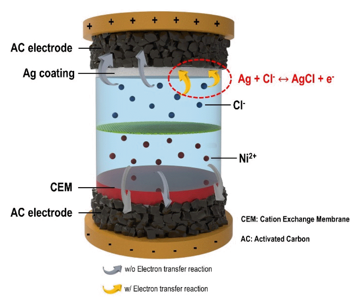
1. IntroductionNickel (Ni) is an essential resource for many industries worldwide, and it is used in stainless steel, non-ferrous alloy, electroplating material, alloy steel, foundries, and other material industries (including batteries) [1]. In addition, Ni complexes have been used as efficient catalysts in synthesis processes [2–4]. Nickel oxide has been used as a major raw material for cathode materials in the battery industry [5]. However, as the industrial use of Ni increases, its impact on environmental pollution is also increasing [6]. Exposure to Ni-contaminated environments causes pathological problems, such as contact dermatitis, pulmonary fibrosis, cardiovascular and renal diseases, and even cancer [6,7]. Therefore, the water quality standard for Ni is strictly managed by the WHO at a value of 0.07 mg/L [8]. Accordingly, effective Ni treatment methods are required.
Conventional Ni wastewater treatment processes include precipitation, adsorption or ion exchange resin methods, ion flotation, and electrochemical processes [9]. However, each technique has limitations. For example, the sedimentation process is not suitable for low-concentration Ni wastewater, and there is a burden on sludge waste treatment [9]. In addition, although the adsorption and ion exchange resin methods are suitable for low-concentration Ni wastewater and have high removal efficiency [10], a large amount of wastewater is generated in the regeneration step [11]. The ion flotation separation method is a simple process with low energy consumption; however, reports indicate that the removal efficiency is poor and ion separation from the collector is limited [12]. The electrochemical method presents selectivity according to the operating conditions, does not use chemicals, and does not generate separate waste. However, it has limitations in that the electrode cost and energy consumption are high [13]. Therefore, an effective water treatment technology for Ni is required.
Capacitive deionization (CDI) is an electrochemical-based water-treatment technology that has recently received attention [14–16]. CDI removes ions from feed water by storing them in the electrical double layer (EDL) of the electrodes. Compared to other electrochemical processes, CDI is advantageous based on its energy consumption because it operates at a low electrical potential and typically uses an inexpensive electrode, such as activated carbon (AC) [17,18]. However, CDI is limited by its low deionization capacity [19]. Various attempts have been made to overcome this low capacity, such as maximizing the electrode area [20–22] and developing CDI systems [23–26]. Among these, hybrid capacitive deionization (HCDI) technology using electron transfer reactions has attracted attention [26]. Manganese oxide-based electrodes have been introduced as HCDI electrodes for Ni treatment; however, few systematic studies (e.g., on the electrochemical stability, energy consumption, and water quality) have been conducted on these systems [27,28]. Recently, silver (Ag)-coated AC electrodes for HCDI were introduced [29,30]. HCDI using Ag-coated AC electrodes showed excellent results in terms of electrochemical stability and energy consumption and presented high deionization performance. However, HCDI with an Ag coating has not been investigated as a Ni treatment.
In this study, we propose an HCDI with an Ag coated AC electrode for Ni treatment. To the best of our knowledge, this is the first attempt to use Ag-coated AC electrodes for Ni treatment. The Ag-coated AC electrode was fabricated using a procedure reported in our previous study [29]. The deionization capacity, deionization rate, and charge efficiency were analyzed to evaluate the effect of the Ag-coated AC electrode. In addition, we attempted to derive the optimal operating conditions by analyzing the charge efficiency, effluent pH, and energy consumption by varying the applied potential.
2. ExperimentalActivated carbon electrodes were fabricated according to our previous research [29–32]. Activated carbon (YP50F, Kuraray Chemical Co., Japan), binder (PTFE, Sigma-Aldrich, USA), and conductive material (Ketjenblack, Mitsubishi Chemical Corp., Japan) were mixed well and extruded, and then the extruded electrode was vacuum-dried at 120°C for more than 12 h. The Ag-coated AC electrodes were prepared according to our previous research [29]. The surface of the AC electrode was maintained in contact with a 100 mM silver nitrate solution for approximately 1 h under UV irradiation. After treatment with the base solution, the electrode was rinsed with distilled water. The weight increase of the electrode due to Ag coating was 1.7 mg/cm2 which was approximately 10% of the AC electrode. Prior to use in the deionization test, the electrode was dried in a vacuum oven at 120°C for 12 h. Electrode characterization was performed using scanning electron microscopy (SEM) (MAGNA FEG Scanning Electron Microscope, Tescan, Czech Republic), cyclic voltammetry (VersaSTAT3, YOUNGIN AT, Republic of Korea), and surface resistivity measurements (MCP-T610, MITSUBISHI corp., Japan).
For the experimental group, the HCDI system was configured as follows. An Ag-coated AC electrode was used as the positive electrode, an AC electrode was used as the negative electrode, and a cation exchange membrane was mounted on the negative electrode (CMV, Selemion™, AGC Engineering Corp., Japan). An MCDI system was used as a control, in which an AC electrode was used for both electrodes and a pair of cation/anion ion exchange membranes were mounted on each electrode (CMV and AMV, Selemion™, AGC Engineering Corp., Japan).
Deionization performance was evaluated in a flow-mode cell with a flow rate of 2 mL/min (Fig. S1 in Supplementary Materials). As a feed solution, 5 mM NiCl2 was used. The ion adsorption/desorption step was performed by applying a constant voltage of 0.5/−0.5 V to 1.1/−1.1 V, respectively. Changes in the ion concentration were analyzed by measuring the conductivity of the effluent (3573-10C, HORIBA, Japan). Fig. 1 shows the conductivity of the solution with respect to the concentration of Ni2+. As shown in Fig. 1, the Ni2+ concentration and solution conductivity showed an excellent positive correlation (R2>0.99).
The deionization capacity, charge efficiency, deionization rate, and energy consumption were calculated as follows:
where Mw is the molecular weight of NiCl2 (129.6 g/mole); Ci and Co are the Ni2+ concentrations of the influent and effluent for the deionization test (mM), respectively; Φ indicates the flow rate (mL/min); t indicates time (min), Me is a mass of the electrode (g), F is a Faradaic constant (96485 C/mole), V indicates the applied voltage (V); and I indicates the current (A).
3. Results & Discussion
Fig. 2 shows the characterization results of the Ag-coated AC electrode. Fig. 2(a) shows a top-view image of the AC electrode before and after the Ag coating. As shown in the results, a distinctive change in the surface color of the Ag-coated electrode was observed compared with that of the pristine AC electrode. It is noted that the electrode weight only increased by approximately 10% based on the Ag coating. Fig. 2(b) and (c) show SEM images of the pristine AC electrode and Ag-coated AC electrode, respectively. As shown in Fig. 2(c), approximately 10 μm Ag was coated onto the AC electrode surface. Fig. 2(d) shows the CV profiles of the AC electrode and Ag-coated AC electrode. As shown in Fig. 2(d), the AC electrode exhibited a rectangular CV profile, which is consistent with a typical capacitive electrode. Thus, the AC electrode stored ions only in the electrical double layer (EDL) of the electrode. In the Ag-coated AC electrode, a pair of peaks were observed at approximately −0.05 to 0.08 V and the CV profile had a rectangular shape, which indicates that the electron transfer redox reaction occurred in the coating of Ag and chloride ions (Ag + Cl− ↔ AgCl + e−) [29,30]. The Ag-coated AC electrode is expected to store ions through the electron transfer reaction between the coated Ag and Cl ions as well as through the EDL of the AC electrode, resulting in an improvement in the deionization performance. Fig. 2(d) shows the surface resistance of the AC electrode and Ag-coated AC electrode. The surface resistance of the activated carbon electrode was 58 ± 7 Ω/square, and the surface resistance of the Ag-coated AC electrode was 44 ± 2 Ω/square, in which the Ag coating reduced the surface resistance by approximately 24%. This is also expected to have a positive effect on the deionization performance. To observe the effect of introducing Ag-coated electrodes in HCDI, the deionization performance of NiCl2 was analyzed.
Fig. 3 (a–c) shows the deionization capacity, deionization rate, and charge efficiency of HCDI with the Ag coating compared to MCDI under 0.5 V/−0.5 V condition, respectively. As shown in Fig. 3, HCDI with the Ag-coated AC outperformed MCDI with the Ag-coated AC. For example, the deionization capacity of HCDI with the Ag coating was approximately 10 mg/g, which was approximately 66% higher than that of MCDI (approximately 6 mg/g) in Fig. 3(a). In Fig. 3(b), the maximum deionization rate of HCDI with the Ag coating (0.036 mg/g/s) is 16% higher than that of MCDI (0.031 mg/g/s). The increased deionization capacity and deionization rate appeared to be due to the increase in the electrochemical capacity of the electrode based on the Ag coating (Fig. 2(d)). The results showed a similar trend to that of a previous study [30]. Previous studies reported that an increase in the electrochemical capacity of one electrode contributes to an increase in the deionization capacity and rate [19,26,30]. In addition, as shown in Fig. 3(c), the charge efficiency of HCDI with the Ag coating (85%) was higher than that of MCDI (64%). The improved charge efficiency of HCDI with the Ag coating compared with that of MCDI appears to be due to the efficient electron transfer reaction between Ag and chloride ions [29]. In the case of general AC electrodes, ‘co-ion repulsion’ occurs in the process of forming an electric double layer (EDL), and a certain portion of the charge efficiency is wasted [33]. However, with the Ag coating, because chloride ions are stored in the Ag coating layer through an electron transfer reaction, the loss of charge efficiency induced by co-ion repulsion can be reduced [29,30], which appears to improve the charge efficiency. To optimize the operating conditions, the effect of applied voltage on the deionization performance of HCDI with the Ag coating for NiCl2 was investigated.
Fig. 4 (a–b) show the deionization capacity and charge efficiency according to the applied voltage. In Fig. 4(a), as the applied voltage increased from 0.5 V to 1.1 V, the deionization capacity increased from 10.0 mg/g to 18.8 mg/g. This improvement in the deionization capacity with applied potential has been typically observed in HCDI systems [26, 29]. Because the capacity of a capacitive electrode depends on the applied voltage, an increase in the applied voltage leads to an increase in the deionization capacity [26]. On the other hand, in Fig. 4(b), the charge efficiency decreased slightly from 84.6% to 77.2% when the applied potential increased from 0.5 V to 1.1 V. Reports indicate that the charge efficiency decreases as the applied voltage increases when there is an electron transfer reaction in a CDI system [34]. Since HCDI with an Ag coating is also a system based on electron transfer reactions, it seems that the charge efficiency decreased due to the increase in the applied potential. However, it still showed a decent charge efficiency of over 77%. The effect of the applied voltage on the pH of the effluent was investigated.
Fig. 5 (a) and (b) show the pH of the effluent of HCDI with the Ag coating and MCDI based on the applied voltage, respectively. As shown in Fig. 5(a), as the applied potential was changed from 0.5 V/−0.5 V to 1.1 V/−1.1 V, the pH of the effluent changed. In the 0.5 V/−0.5 V section, the pH of the effluent was maintained at approximately 7.2, whereas in the 0.7 V/−0.7 V section, a change in pH was observed from. As shown in Fig. 5(a), the pH of the effluent changed from 7.2 to 6.25. Considering that the pH of the effluent was below 7, hydrogen ions appeared to be produced during the electrochemical reaction. Nevertheless, the operating condition of 0.7 V/−0.7 V would be acceptable when taking into account the domestic drinking water guideline (pH 5.8 – 8.5) [35]. However, the pH change intensified in the 0.9 V/−0.9 V and 1.1 V/−1.1 V sections. The pH in the 0.9 V/−0.9 V section changed from 7.2 to 5.2, and the pH in the 1.1 V/−1.1 V section changed from 7.2 to 4.3. Therefore, when operating under 0.9 V/−0.9 V and 1.1 V/−1.1 V conditions, the effluent pH exceeds the drinking pH range. Similar results were observed for MCDI (Fig. 5(b)). Therefore, when considering the pH guidelines for drinking water, operating at a low operating potential of 0.7 V or less is recommended.
As shown in Fig. 6, the CV profile of the AC electrode in NiCl2 solution was compared to that in NaCl solution. As shown in Fig. 6, in the case of the NiCl2 solution, the current was caused by the electron transfer reaction. For example, an increase in the reduction current was observed when the potential was below −0.45 V (vs Ag/AgCl) and an increase in the oxidation current was observed above −0.2 V (vs Ag/AgCl). In the case of the NaCl solution, no significant change of current was observed in the range of −0.7 to approximately 0.3 V (vs Ag/AgCl). This indicated that no electron transfer reaction occurred. Therefore, the electron transfer reaction observed in the CV of NiCl2 was due to the Ni2+ ion. Considering that the standard reduction potential of Ni is approximately −0.45 V vs Ag/AgCl (i.e., −0.23 V vs RHE), the reduction current at −0.45 V (vs Ag/AgCl) observed in Fig. 6 may have been due to a Ni metallic deposition reaction [36]. In addition, in the negative direction of the electrical potential, an increase in oxidation current was observed at −0.2 V (vs Ag/AgCl), suggesting that dissolution of the deposited Ni occurred [37]. The CV results shown in Fig. 6 explain the pH results shown in Fig. 5. Because the reduction of Ni ions occurs at a relatively low electrical potential (−0.23 V vs RHE), an electron transfer reaction potential for generating hydrogen ions at the positive electrode (at the adsorption step) may be reached under the high applied voltage condition [38]. Accordingly, as the applied voltage of the deionization operation increases, the electron transfer reaction in which hydrogen ions are generated is intensified and the pH is changed (in Fig. 5). It is noted that other potent reduction reactions are the formation of Ni(OH)2 and NiOOH, but their reduction potentials are quite far from that observed in Fig. 6 (ex. 0.2 V vs RHE for Ni(OH)2 and 1.35 V vs. RHE for NiOOH) [39].
Fig. 7 shows the energy consumption of the MCDI and HCDI systems with the Ag coating at the applied voltage (Eq. (4)). In Fig. 7, two important observations can be made. First, at a lower applied voltage, the energy consumption is lower. Second, the energy consumption of HCDI with the Ag coating is lower than that of MCDI. For example, when the applied potential is 0.5 V, MCDI consumes 0.33 Wh/g-NiCl2 and HCDI with the Ag coating consumes 0.24 Wh/g-NiCl2. When the applied potential is 1.1 V, MCDI consumes 0.73 Wh/g-NiCl2 and HCDI with the Ag coating consumed 0.59 Wh/g-NiCl2 energy. In general, the energy consumption depends on the applied voltage as shown in Eq. (4). Therefore, it is predictable that the lower the applied potential, the lower the energy consumption. On the other hand, the fact that the HCDI with the Ag coating consumes less energy than the MCDI under all applied voltage conditions is a significant result, especially considering that HCDI with Ag coating outperforms MCDI in terms of deionization performance (refer to Fig. 3). The better energy efficiency of HCDI with the Ag coating than MCDI under the identical applied voltage seems to be due to the difference in charge efficiency between the two systems. The charge efficiency of HCDI with the Ag coating was better than that of the MCDI (Fig. 3 (c)). It was reported that the Ag-coated AC electrode in the HCDI system could reduce charge waste via co-ion repulsion compared with the pristine AC electrode [29]. Therefore, this HCDI system using Ag coated AC electrode seems to have a positive effect on energy consumption in comparison with the conventional MCDI system only using the AC electrode.
This study used a constant voltage operation mode to focus on improving deionization capacity, but according to previous study, it was reported that energy efficiency is enhanced when constant current (CC) operation mode is used [40]. Thus, in the future, the research on CC mode should be investigated to maximize energy consumption efficiency.
Fig. 8 shows the electrochemical capacity ratio of HCDI with the Ag-coated AC electrode. As shown in Fig. 8, approximately 95% of the electrochemical capacity is maintained for 300 cycles. In addition, the ratio of the discharge capacity to the charge capacity (i.e., coulombic efficiency) reached approximately 99%. As shown in Fig. 8, this system exhibited excellent electrochemical stability. However, the stability of the electrochemical capacity cannot directly guarantee the stability of the deionization performance. The stability of the deionization performance of the HCDI system for Ni treatment will be systematically investigated in our future research.
4. ConclusionsIn this study, an HCDI system with an Ag-coated AC electrode for Ni treatment was proposed. A major finding was that the deionization capacity of HCDI with the Ag-coated AC electrode was approximately 66% greater than that of the MCDI system. In addition, as the applied potential was increased from 0.5 V to 1.1 V, the deionization capacity improved from 10 mg/g to 18 mg/g, although the charge efficiency partially decreased from 84.6% to 77.2%. When the applied potential was 0.9 V or more, the pH of the effluent exceeded the drinking water quality standard, which appears to be associated with the electron transfer reaction between the Ni2+ ion and the electrode. In terms of energy consumption, HCDI with Ag coatings achieved 0.24 Wh/g-NiCl2 as a minimum value. The results of this study are expected to contribute to the applicability of CDI technology for Ni treatments in the future.
AcknowledgmentsThis work was supported by a National Research Foundation of Korea (NRF) grant funded by the Korean government (NRF – 2020R1C1C1012688) and This work was supported by Development of key technologies for safety management of hydrogen charging infrastructure (1415180603) and the Development of Green Hydrogen Production and Storage System (1415180938) funded by the Korea Government Ministry of Trade, Industry and Energy and by the New and renewable energy core technology development project of the Korea Institute of Energy Technology Evaluation and Planning(KETEP) granted financial resource from the Ministry of Trade, Industry & Energy, Republic of Korea(No. 20213030040590).
References1. Reck BK, McesntributRostkowski K, Graedel TE. Anthropogenic nickel cycle: insights into use, trade, and recycling. Environ. Sci. Technol. 2008;42(9)3394–3400.
https://doi.org/10.1021/es072108l
2. Marafi M, Stanislaus A. Spent catalyst waste management: a review. Resour. Conserv. Recy. 2008;52(6)859–873.
https://doi.org/10.1016/j.resconrec.2008.02.004
3. Marafi M, Stanislaus A. Spent hydroprocessing catalyst management: a review. Resour. Conserv. Recy. 2008;53(1–2)1–26.
https://doi.org/10.1016/j.resconrec.2008.08.005
4. Perosa A, Tundo P. Selective hydrogenolysis of glycerol with Raney nickel. Ind. Eng. Chem. Res. 2005;44(23)8535–8537.
https://doi.org/10.1021/ie0489251
5. Shukla AK, Venugopalan S, Hariprakash B. Nickel-based rechargeable batteries. J. Power Sources. 2001;100(1–2)125–148.
https://doi.org/10.1016/S0378-7753(01)00890-4
6. Denkhaus E, Salnikow K. Nickel essentiality, toxicity, and carcinogenicity. Crit. Rev. Oncol. Hematol. 2002;42(1)35–56.
https://doi.org/10.1016/s1040-8428(01)00214-1
7. Kasprzak KS, Sunderman FW, Salnikow K. Nickel carcinogenesis. Mutat. Res. 2003;533(1–2)67–97.
https://doi.org/10.1016/j.mrfmmm.2003.08.021
8. World Health Organization. Nickel in drinking water: background document for development of WHO Guidelines for drinking-water quality. World Health Organization; (No. WHO/HEP/ECH/WSH/2021.6)2021.
9. Shrestha R, Ban S, Devkota S, Sharma S, Joshi R, Tiwari AP, et al. Technological trends in heavy metals removal from industrial wastewater: a review. J. Environ. Chem. Eng. 2021;9(4)105688.
https://doi.org/10.1016/j.jece.2021.105688
10. Karnib M, Kabbani A, Holail H, Olama Z. Heavy metals removal using activated carbon, silica and silica activated carbon composite. Energy Procedia. 2014;50:113–120.
https://doi.org/10.1016/j.egypro.2014.06.014
11. Qi X, Xie F. Promotion effects of potassium permanganate on removal of Pb(II), Ni(II) and Cd(II) from hydrous manganese dioxide. Chem. Eng. J. 2018;351:22–30.
https://doi.org/10.1016/j.cej.2018.06.042
12. Peng W, Chang L, Li P, Han G, Huang Y, Cao Y. An overview on the surfactants used in ion flotation. J. Mol. Liq. 2019;286:110955.
https://doi.org/10.1016/j.molliq.2019.110955
13. Abdel-Raouf MS, Abdul-Raheim ARM. Removal of heavy metals from industrial waste water by biomass-based materials: a review. J. Pollut. Eff. Control. 2017;5:1–13.
https://doi.org/10.4172/2375-4397.1000180
14. Porada S, Zhao R, Van Der Wal A, Presser V, Biesheuvel PM. Review on the science and technology of water desalination by capacitive deionization. Prog. Mater. Sci. 2013;58(8)1388–1442.
https://doi.org/10.1016/j.pmatsci.2013.03.005
15. Suss ME, Porada S, Sun X, Biesheuvel PM, Yoon J, Presser V. Water desalination via capacitive deionization: what is it and what can we expect from it? Energy Environ. Sci. 2015;8(8)2296–2319.
https://doi.org/10.1039/C5EE00519A
16. Yoon H, Lee J, Kim S, Yoon J. Review of concepts and applications of electrochemical ion separation (EIONS) process. Sep. Purif. Technol. 2019;215(15)190–207.
https://doi.org/10.1016/j.seppur.2018.12.071
17. Anderson MA, Cudero AL, Palma J. Capacitive deionization as an electro-chemical means of saving energy and delivering clean water. Comparison to present desalination practices: will it compete? Electrochim. Acta. 2010;55(12)3845–3856.
https://doi.org/10.1016/j.electacta.2010.02.012
18. Zhao R, Porada S, Biesheuvel PM, Van der Wal A. Energy consumption in membrane capacitive deionization for di2016/j.electarecoveries and flow rates, and comparison with reverse osmosis. Desalination. 2013;330:35–41.
https://doi.org/10.1016/j.desal.2013.08.017
19. Kim T, Yoon J. Relationship between capacitance of activated carbon composite electrodes measured at a low electrolyte concentration and their desalination performance in capacitive deionization. J. Electroanal. Chem. 2013;704:169–174.
https://doi.org/10.1016/j.jelechem.2013.07.003
20. Wimalasiri Y, Zou L. Carbon nanotube/graphene composite for enhanced capacitive deionization performance. Carbon. 2013;59:464–471.
https://doi.org/10.1016/j.carbon.2013.03.040
21. Zhang D, Wen X, Shi L, Yan T, Zhang J. Enhanced capacitive deionization of graphene/mesoporous carbon composites. Nanoscale. 2012;4(17)5440–5446.
https://doi.org/10.1039/c2nr31154b
22. Mayes RT, Tsouris C, Kiggans JO, Mahurin SM, DePaoli DW, Dai S. Hierarchical ordered mesoporous carbon from phloroglucinol-glyoxal and its application in capacitive deionization of brackish water. J. Mater. Chem. 2010;20(39)8674–8678.
https://doi.org/10.1039/c0jm01911a
23. Jeon S-i, Park H-r, Yeo J-g, Yang S, Cho CH, Han MH, et al. Desalination via a new membrane capacitive deionization process utilizing flow-electrodes. Energy Environ. Sci. 2013;6(5)1471–1475.
https://doi.org/10.1039/c3ee24443a
24. Gao X, Omosebi A, Landon J, Liu K. Enhanced salt removal in an inverted capacitive deionization cell using amine modified microporous carbon cathodes. Environ. Sci. Technol. 2015;49(18)10920–10926.
https://doi.org/10.1021/acs.est.5b02320
25. Lee J-B, Park K-K, Eum H-M, Lee C-W. Desalination of a thermal power plant wastewater by membrane capacitive deionization. Desalination. 2006;196(1–3)125–134.
https://doi.org/10.1016/j.desal.2006.01.011
26. Lee J, Kim S, Kim C, Yoon J. Hybrid capacitive deionization to enhance the desalination performance of capacitive techniques. Energy Environ. Sci. 2014;7(11)3683–3689.
https://doi.org/10.1039/C4EE02378A
27. Li P, Gui Y, Blackwood DJ. Development of a nanostructured 39/C4EE02378A” \t “_blank” performance of capacitive techniquesous carbon cath. ACS Appl. Mater. Interfaces. 2018;10(23)19615–19625.
https://doi.org/10.1021/acsami.8b02471
28. Liu L, Qiu G, Suib SL, Liu F, Zheng L, Tan W, et al. Enhancement of Zn2+ and Ni2+ removal performance using a deionization pseudocapacitor with nanostructured birnessite and its carbon nanotube composite electrodes. Chem. Eng. J. 2017;328:464–473.
https://doi.org/10.1016/j.cej.2017.07.066
29. Yoon H, Lee J, Kim S, Yoon J. Hybrid capacitive deionization with Ag coated carbon composite electrode. Desalination. 2017;422:42–48.
https://doi.org/10.1016/j.desal.2017.08.010
30. Yoon H, Lee J, Min T, Lee G, Oh M. High performance hybrid capacitive deionization with a Ag-coated activated carbon electrode. Environ. Sci.: Water Res. Technol. 2021;7(7)1315–1321.
https://doi.org/10.1039/D1EW00209K
31. Yoon H, Min T, Lee G, Park I, Han B, Kang BS, et al. Development of capacitive deionization with calcium alginate based cation exchange membrane for hardness control. J. Korean Soc. Ind. Converg. 2021;24:563–571.
https://doi.org/10.21289/KSIC.2021.24.5.563
32. Yoon H, Lee J, Kim SR, Kang J, Kim S, Kim C, et al. Capacitive deionization with Ca-alginate coated-carbon electrode for hardness control. Desalination. 2016;392:46–53.
https://doi.org/10.1016/j.desal.2016.03.019
33. Biesheuvel PM, Van der Wal A. Membrane capacitive deionization. J. Membr. Sci. 2010;346(2)256–262.
https://doi.org/10.1016/j.memsci.2009.09.043
34. Kim T, Yu J, Kim C, Yoon J. Hydrogen peroxide generation in flow-mode capacitive deionization. J. Electroanal. Chem. 2016;776:101–104.
https://doi.org/10.1016/j.jelechem.2016.07.001
35. Lee JY, Bak G, Han M. Quality of roof-harvested rainwater comparison of different roofing materials. Environ. Pollut. 2012;162:422–429.
https://doi.org/10.1016/j.envpol.2011.12.005
36. Bard A. Standard potentials in aqueous solution. Routledge; 2017.
37. Omar IMA, Emran KM, Aziz M, Al-Fakih AM. A novel viewpoint of an imidazole derivative ionic liquid as an additive for cobalt and nickel electrodeposition. RSC Adv. 2020;10(53)32113–32126.
https://doi.org/10.1039/d0ra06510b
38. Yu J, Jo K, Kim T, Lee J, Yoon J. Temporal and spatial distribution of pH in flow-mode capacitive deionization and membrane capacitive deionization. Desalination. 2018;439:188–195.
https://doi.org/10.1016/j.desal.2018.04.011
39. Alsabet M, Grdeń M, Jerkiewicz G. Electrochemical growth of surface oxides on nickel. Part 3: Formation of β-NiOOH in relation to the polarization potential, polarization time, and temperature. Electrocatalysis. 2015;6(1)60–71.
https://doi.org/10.1007/s12678-014-0214-1
40. Kang J, Kim T, Jo K, Yoon J. Comparison of salt adsorption capacity and energy consumption between constant current and constant voltage operation in capacitive deionization. Desalination. 2014;352:52–57.
https://doi.org/10.1016/j.desal.2014.08.009
Fig. 2Characterization of the AC electrode and Ag-coated AC electrode: (a) top view of the AC electrode and Ag-coated AC electrode; SEM top view of the (b) AC electrode and (c) Ag-coated AC electrode; (d) cyclic voltammetry profiles; and (e) surface resistivity (electrolyte: 2 M LiCl; scan rate: 1 mV/s; and reference electrode: Ag/AgCl KCl sat’d). To observe the effect of introducing Ag-coated electrodes in HCDI, the deionization performance of NiCl2 was analyzed. 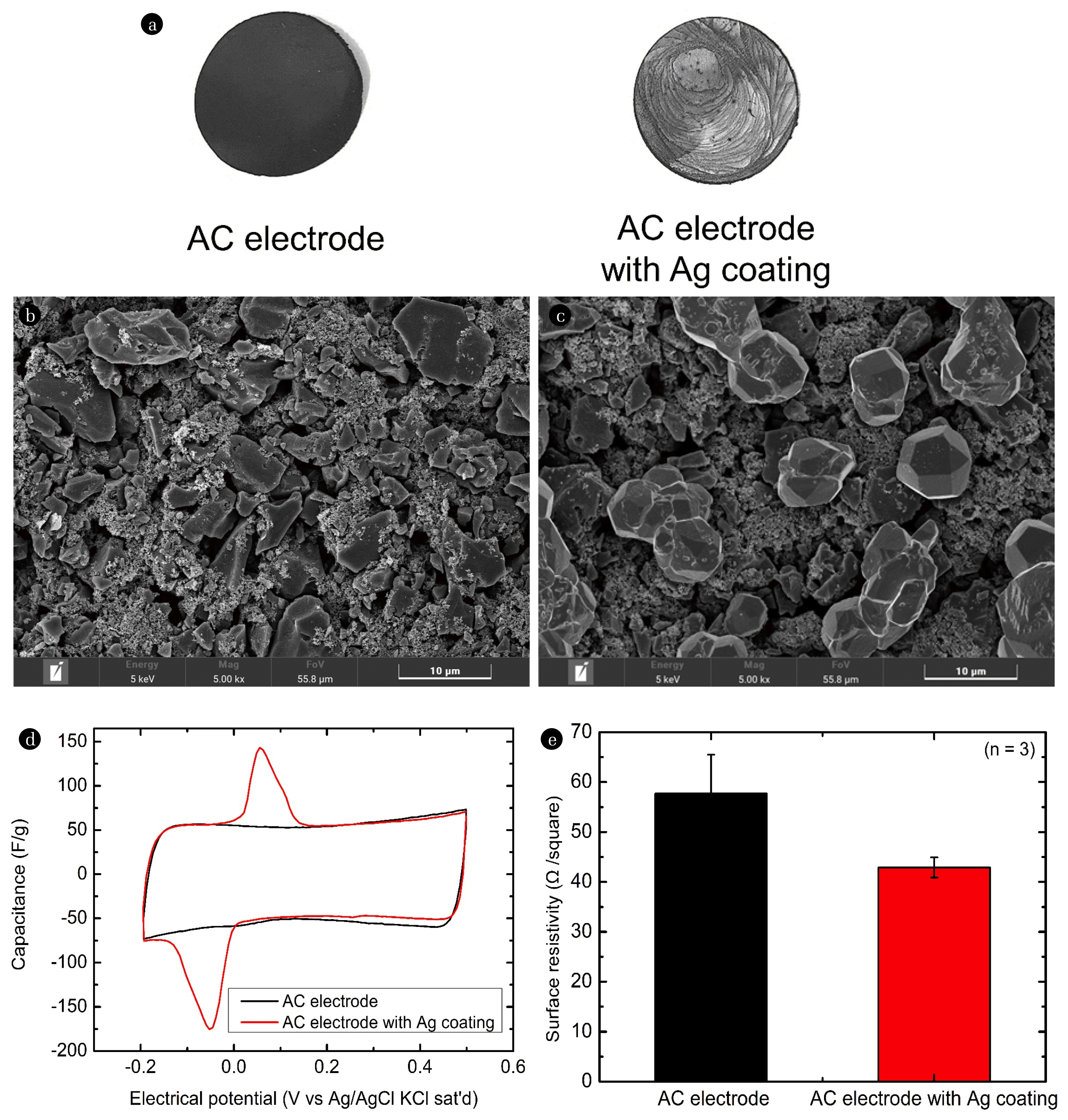
Fig. 3Ni deionization performance of MCDI and HCDI with Ag coating: (a) deionization capacity, (b) deionization rate, and (c) charge efficiency (feed: 5 mM NiCl2; negative electrode: AC electrode; positive electrode: AC electrode or Ag-coated AC electrode; applied voltage: 0.5/−0.5 V; and flow rate: 2 mL/min). MCDI: membrane capacitive deionization; HCDI: hybrid capacitive deionization; and AC: activated carbon. 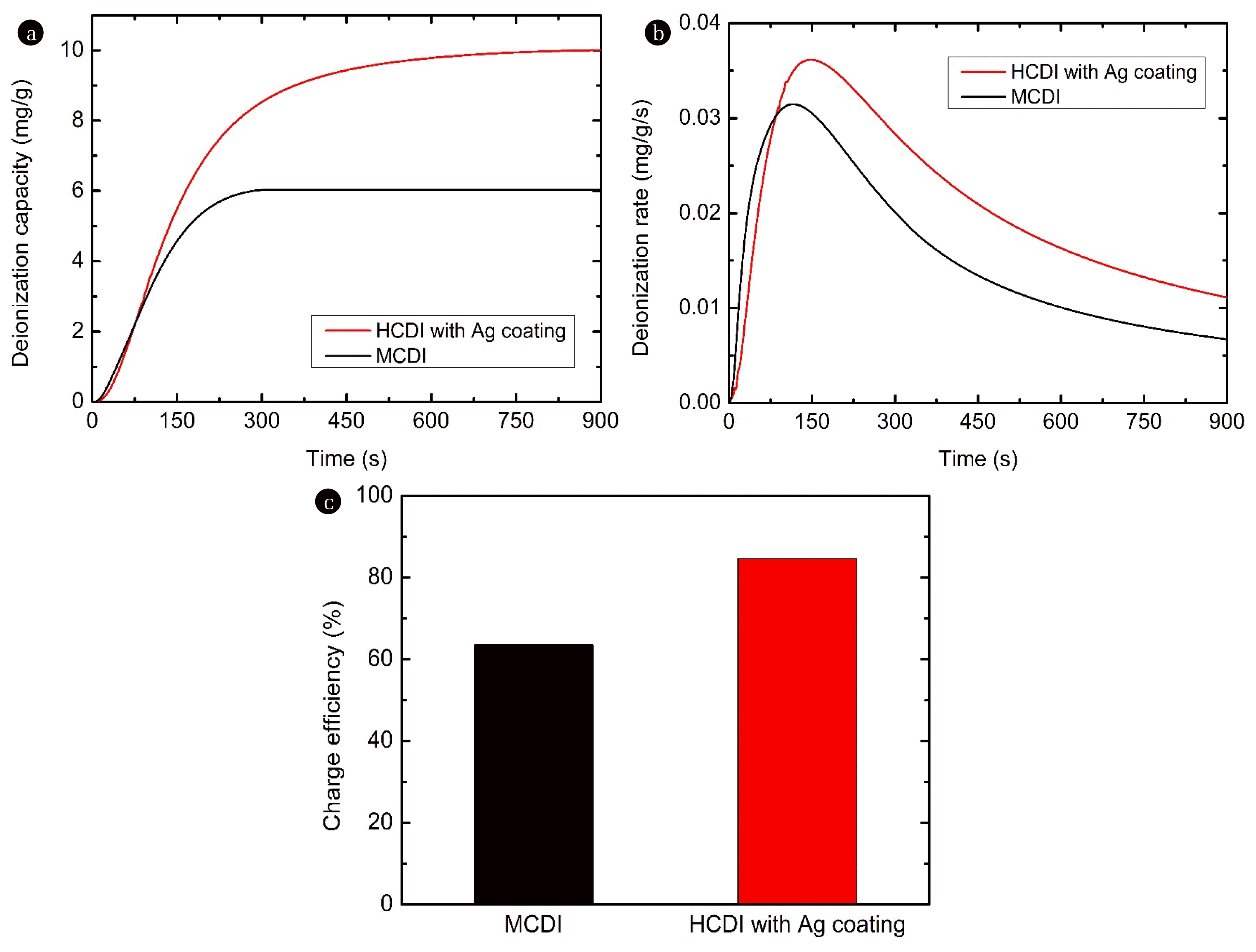
Fig. 4Effect of the applied voltage on the Ni deionization performance of HCDI with an Ag coating: (a) deionization capacity and (b) charge efficiency (feed: 5 mM NiCl2; negative electrode: AC electrode; positive electrode: AC electrode or Ag-coated AC electrode; applied voltage: 0.5/−0.5 V ~ 1.1/−1.1 V; and flow rate: 2 mL/min). HCDI: hybrid capacitive deionization; and AC: activated carbon. 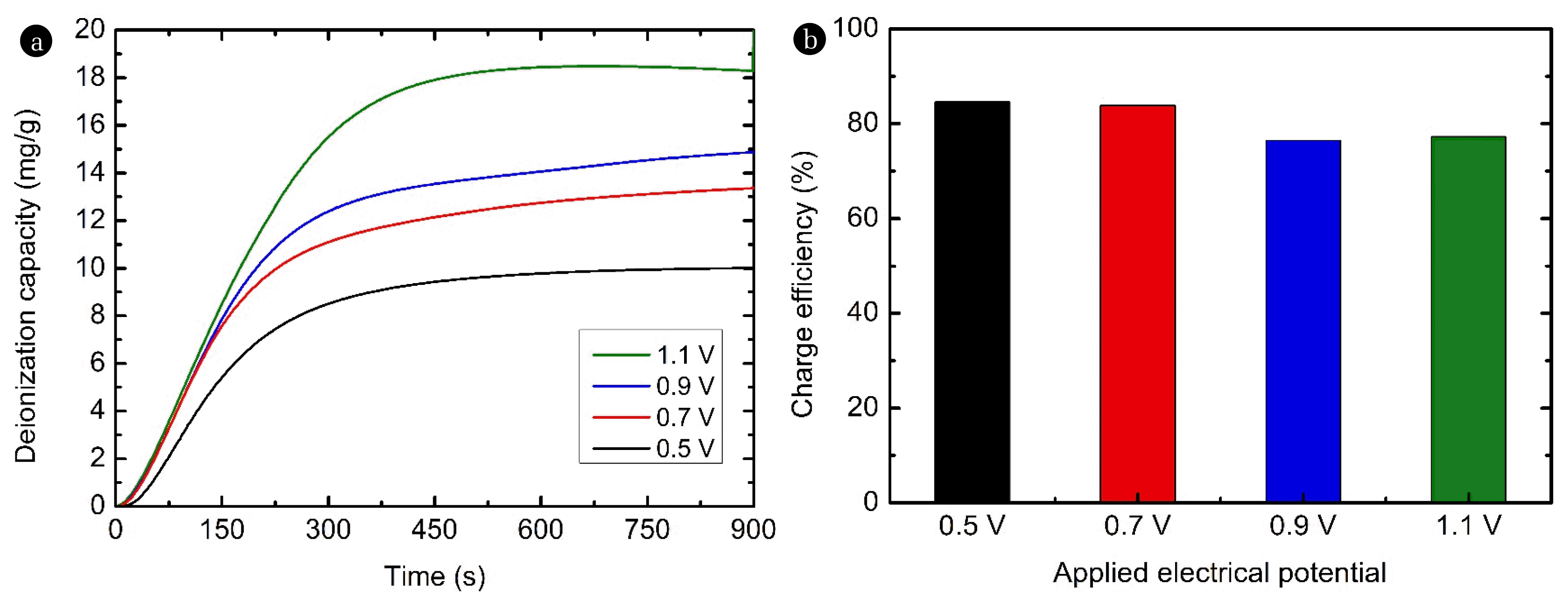
Fig. 5Effect of the applied voltage on the pH of the effluent of the (a) HCDI with Ag coating system and (b) MCDI system (feed: 5 mM NiCl2; negative electrode: AC electrode; positive electrode: Ag-coated AC electrode; applied voltage: 0.5/−0.5 V ~ 1.1/−1.1 V for 2 cycles each; and flow rate: 2 mL/min). HCDI: hybrid capacitive deionization; AC: activated carbon; and MCDI: membrane capacitive deionization. 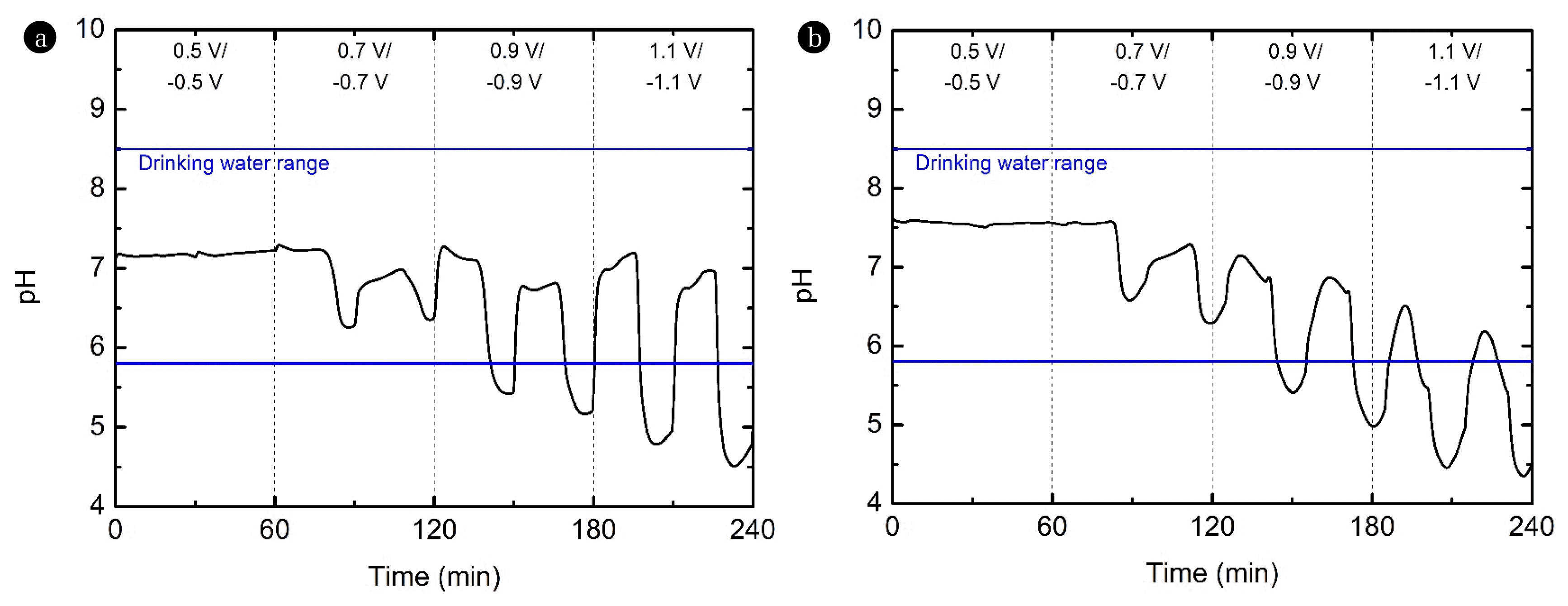
Fig. 6Cyclic voltammetry profile of the activated carbon electrode in NaCl or NiCl2 solution (electrolyte: 2 M NaCl or 1 M NiCl2; Scan rate: 5 mV/s). 
|
|
|||||||||||||||||||||||||||||||||||||||||