This is an Open Access article distributed under the terms of the Creative Commons Attribution Non-Commercial License (http://creativecommons.org/licenses/by-nc/3.0/) which permits unrestricted non-commercial use, distribution, and reproduction in any medium, provided the original work is properly cited.
Abstract
As regulations governing the control of volatile organic compounds (VOCs) have become increasingly stringent in China, regenerative thermal oxidizers (RTOs) have been more frequently applied in medium- and high-concentration VOCs treatments. However, due to the lack of existing RTO-related research, experience remains a dominant factor for industrial application. This paper thus aimed to establish a model for industrial RTOs, using a transient simulation method and thermal equilibrium model to simulate the internal velocities and temperature distributions of an RTO across multiple cycles. A comparison showed an error of less than 5% between most correlating simulated and experimental measurement points, verifying that the simulation method was accurate. After verification, the velocity and temperature fields inside the RTO were simulated to study the uniformity of temperature and velocity within the packed beds: both fields displayed high uniformity after gas flowed through the honeycomb regenerator. The effects of air volume, VOCs concentrations, and valve switching times on the oxidation chamber temperature, RTO outlet temperature, and thermal efficiency (as well as their averages) were studied. The VOCs removal rate in this study was constantly above 98%, and the average thermal efficiency reached 90%.
The petrochemical, shoemaking, and coating industries produce volatile organic compounds (VOCs) that are then released into the atmosphere. Not only are these VOCs important precursors in PM2.5 formation, increasing atmospheric ozone content [1], but the International Agency for Research on Cancer has confirmed that some VOCs are toxic and carcinogenic. The impact of VOCs on the environment and human beings thus cannot be ignored [2–3].
There are multiple VOCs treatment methods, including membrane separation, activated carbon adsorption, liquid absorption, biotransformation, and oxidation. Each VOCs removal method has limitations dictated by the VOCs concentration, air volume, and VOCs species. The oxidation process, transforming VOCs into environmentally friendly CO2 and H2O, is comprised of direct, regenerative, and catalytic oxidation steps [4–7]. The regenerative oxidation method is widely used because of its high VOCs removal rate and high thermal efficiency, allowing it to be employed instead of other oxidation mechanisms.
Regenerative combustion technology has already been applied in other areas: regenerative furnaces for preheating gas, regenerative hot blast furnaces for sending hot air, regenerative heat exchangers for heat exchanges, etc. However, the structures and operating parameters of these devices differ significantly because of their different functions [8–10]. Compared to other devices, regenerative thermal oxidizers (RTOs) operate at low temperatures with high thermal efficiencies and low-pressure losses. Unlike other regenerative combustion devices, VOCs treated in RTOs can act as fuel. When VOCs concentrations reach a certain value, RTOs can be operated without fuel.
RTOs have several advantages, namely, high VOCs removal rates, high thermal efficiency, and economic operation. Industrial experiments have shown the VOCs removal rate of RTOs may reach 96%, an over 70% energy savings relative to conventional direct oxidation equipment [11–12]. Additional calculations found RTO operating costs accounted for a reasonable proportion of this amount [13]. Not only do RTOs display high thermal efficiencies and VOCs removal rates, they produce no secondary pollution during operation. As the oxidation chamber temperature (OCT) primarily ranges between 900–1,100 K, NOx generation is negligible.
Stable RTO operation requires uniform flow and temperature fields. The principle parameters influencing these fields include the air volume, VOCs concentrations, and valve switching time. The effects of these three parameters on two-chamber RTOs have been experimentally studied [14–16], and the influences of gas velocity and temperature change over time have been simulated for three-chamber RTOs [17]. Simulation results, verified by engineering experiments, demonstrated the exhaust gas removal efficiency was over 97% at various exhaust gas concentrations [18]. However, the above literature analysis indicated current simulation studies cannot keep up with the rapid development of VOCs processing methods and that the existing depth of research is insufficient for the extensive application of RTOs in China. The current situation is as follows: 1) simulated temperature fields have not been verified by engineering experiments and results thus lack reliability, 2) most simulations have used steady-state calculations incapable of reflecting temperature changes over time, and 3) little research has been performed regarding the temperature and flow fields inside RTOs.
Simulation studies have two advantages: low costs and high accuracy. Considering the above problems, this paper therefore verified the accuracy of a proposed simulation model by performing engineering experiments first. Variations in RTO characteristic parameters (air volume, VOCs concentration, and valve switching time) were then investigated, generating results that may be used to provided reference for future RTO research in China and abroad.
2. Model and Methods
2.1. Model Introduction
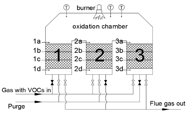
As shown in Fig. 1, the RTO evaluated in this study has three packed beds. The RTO is 3,700 mm long, 900 mm wide and 2,500 mm high. There are three layers of regenerators in each packed bed, and each layer has 36 individual regenerators. Each regenerator is made of porous cordierite and has a length and width of 150 mm and a height of 300 mm. Table 1 provides the primary physical properties of the regenerator. Thermocouples are placed in both the RTO packed beds and the oxidation chamber. The thermocouples in the packed beds are labeled a through d, and the depth that each thermocouple is inserted into the RTO is 200 mm.
The RTO evaluated in this study, each packed bed conducts three processes (intake, exhaust, and purge), each process is achieved by altering a valve switching sequence, a period consists of one complete valve switching sequence, and a cycle contains three switching sequences.
Gas first passes through packed bed 1, where it absorbs heat to warm up. When it enters the oxidizer chamber, it approaches or reaches its ignition point, and then absorbs a portion of the heat to be oxidized. The oxidized high-temperature flue gas then flows through the packed bed 2, where heat is released into the regenerators and then discharged. Next, packed bed 3 removes the exhaust gas remaining in the regenerators from the previous period, blows it into the oxidation chamber for oxidation, and increases the removal rate of VOCs. Once this process is completed, valves switch and packed bed 2 performs the intake process, packed bed 3 performs the exhaust process, and packed bed 1 conducts the purge process. One cycle consists of three periods. The gas flow direction and packed beds operating conditions of one cycle are shown in Table 2.
2.2. Simulation Method
Experimental data were gathered from a RTO in a coating plant in the Jiangsu Province, used to remove organic waste gases from the coating line. The major VOCs components were methanol, xylene, and ethyl acetate, with a volume ratio of 36:7:5. The RTO capacity was 2,500 m3/h, the VOCs concentration was approximately 4,000 mg/m3, the valve switching time was 2 min, the empty packed beds chamber velocity was 0.857 m/s, the OCT was set to 930 K (set burner temperature), and the gas residence time in the oxidation chamber was greater than 1 s. The thermocouple distribution in the RTO can be seen in Fig. 1. The temperature value of all thermocouples was recorded in each period for the experiment. OCTs were calculated as the averaged temperatures of the three relevant thermocouples.
The RTO studied in this paper was imported into a meshing software after a three-dimensional model was established, dividing the structure into a total of 450,000 high-quality structure meshes, and then simulated using appropriate simulation software. The k-ɛ model is a semi-empirical formula that is derived from the experimental phenomena and has a wide range of application and reasonable accuracy. Therefore, the k-ɛ model was used for flow simulation. The eddy dissipation model ignores the complex and unknown chemical reaction kinetics and considers the effect of turbulence on chemical reactions, and therefore the eddy dissipation model was used for combustion. The heat balance model can accurately reflect the simulation results of the regenerator and reduce the amount of calculations, and therefore the heat balance model was used for the regenerators in porous media. The following assumptions were used for simulation calculations:
Industrial applications are heavily insulated, allowing simulation boundary conditions to be set at insulation values. The temperature at the top of the RTO temperature was found to be ~318 K, and the other wall ~303 K,
Methanol content was more than 75% of total VOCs, and VOCs flash points were similar. As the reaction mechanism of methanol is more mature, the composition of the VOCs was assumed to be methanol,
Gas can be sufficiently heat-exchanged with the regenerators in the packed beds,
The OCT was set at 930 K (a lower temperature), allowing oxidation chamber heat transfer by radiation to be ignored,
Auxiliary fuel consumption was experimentally determined to be < 1 m3/h, accounting for a minute portion of the VOCs burning heat. Natural gas consumption was thus ignored in the simulation (oxidation chamber did not add natural gas).
The first portion of simulation calculations were used to verify model accuracy. Based on the experimental data, the temperature distribution inside the RTO under stable operation was estimated, then multiple cycles under unsteady conditions were calculated until a stable temperature was reached. The calculated data were then compared to the experimental data and the stable data were analyzed. In this paper, the velocity inlet and pressure outlet were used as RTO simulation boundary conditions. The empty packed beds chamber velocity was 0.857 m/s, the relative pressure was −300 Pa, the intake air temperature was 343 K, the oxidation chamber initial temperature was 923 K, and the relative pressure of the packed beds outlet was −1,150 Pa.
The second portion of simulation data were used to simulate the cases detailed in Table 3, for which each case was switched during multiple cycles in the calculation (for example, after one period was completed, the intake packed bed was redefined as the purge packed bed, the exhaust packed bed was redefined as the intake packed bed, and the purge packed bed was redefined as the exhaust packed bed). The time step calculated for each case was 1 s, and 120 steps were calculated for each time step. The calculation time for each case was thus > 10 d.
3. Results and Discussion
3.1. Model Accuracy Verification
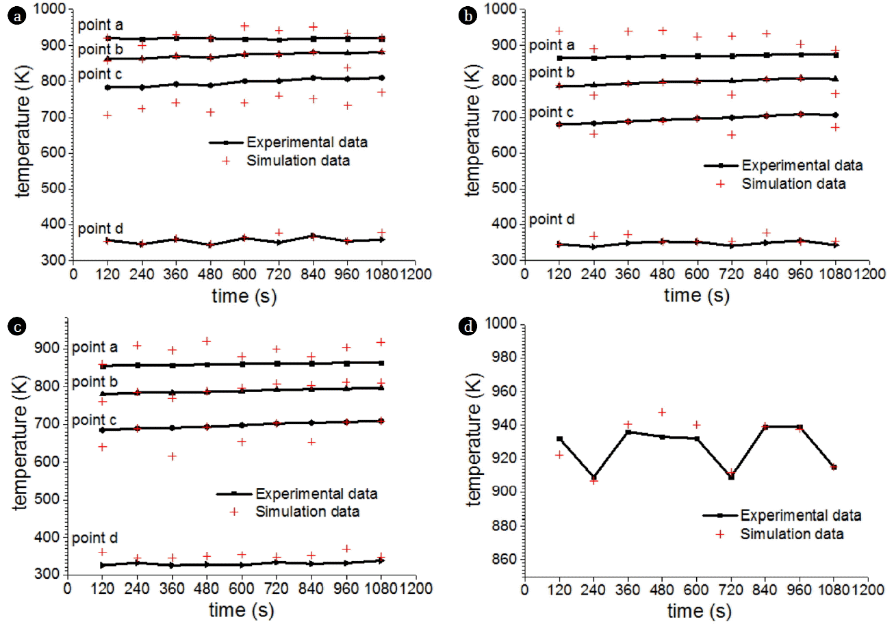
Experimental and simulation values were compared, as shown in Fig. 2 (selected from three cycles). As the figure demonstrates, the packed beds temperature and the OCT differences between the simulated and experimental values were not large and acceptable. And the variation of experimental data and simulation ones were basically the same. Table 4 shows a comparison of the averaged simulated and experimental data in each experimental point. The relative errors between most experimental and simulated values were within 5%; however, other points were smaller than 8.5%. These results verified that simulated results can fairly and accurately reflect the temperature inside the RTO. This proves that the simulation method can be used to systematically study the gas temperature and velocity of the RTO.
Although the experimental data were tried to collect when the RTO was operating stable, there were complex problems in the industry equipment, such as raw material replacing every 3–4 h, human factors in the RTO installation process, ash or resin covering thermocouples, and gases leakage in pipes and valves. All of the factors above would cause errors.
3.2. Packed Beds Uniformity Analysis
The gas in the RTO was evenly distributed under ideal operating conditions, allowing a uniform residence time to be used for gas within the packed beds. This facilitated heat transfers for gas in the packed beds. The uniform distribution of fluid velocity and temperature is beneficial to physical operation of the RTO. The uniformity was analyzed by calculating the coefficient of variation of velocity and temperature in the planes at different heights of the packed beds. The coefficient of variation is a measure of relative variability equal to the standard deviation divided by the mean (see Eq. (1)). Because it is a dimensionless number, it can be used to compare overall discreteness with significantly different means.
CV (Coefficient of Variance): The ratio of standard deviation to mean, formulated as:
(1)
where σ is the standard deviation and μ is the average.
Simulation data verifying correctness were used here to analyze gas velocity and temperature uniformity of the packed beds. The RTO packed beds with three regenerator layers were defined by four planes: the top plane on the top regenerator, the bottom plane under the regenerator bottom, and two adjacent regenerator planes. Each plane’s velocity and temperature coefficient of variation were calculated. Their coefficients of variation are shown in Table 5. It can be seen the coefficients of variation were very small for all planes, further illustrating the even distribution of velocity and temperature inside the RTO packed beds.
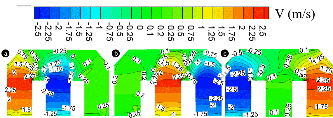
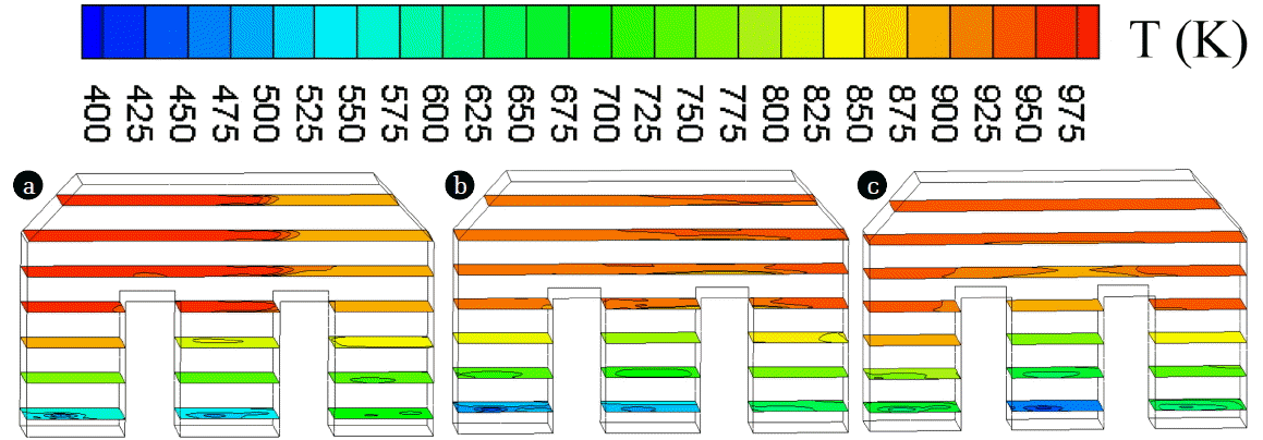
Fig. 3 and Fig. 4 show the Y-axis velocity distributions of the RTO in one cycle for the vertical and horizontal sections, respectively. Velocity uniformity was poor at the bottom of the packed beds due to the sudden expansion of gas exiting the pipe into the packed beds. As the gas flowed upwards through the regenerators, the horizontal section velocity gradually became uniform under the current-sharing effect of small holes in the regenerators; likewise, the downward air flow into the regenerators became gradually uniform. Airflow in the oxidation chamber (an empty room) was uneven due to air flow steering and other factors. Although the gas flow through the corners of the packed beds caused a large velocity gradient, the chambers on either side of the oxidation chamber prevented vortexes.
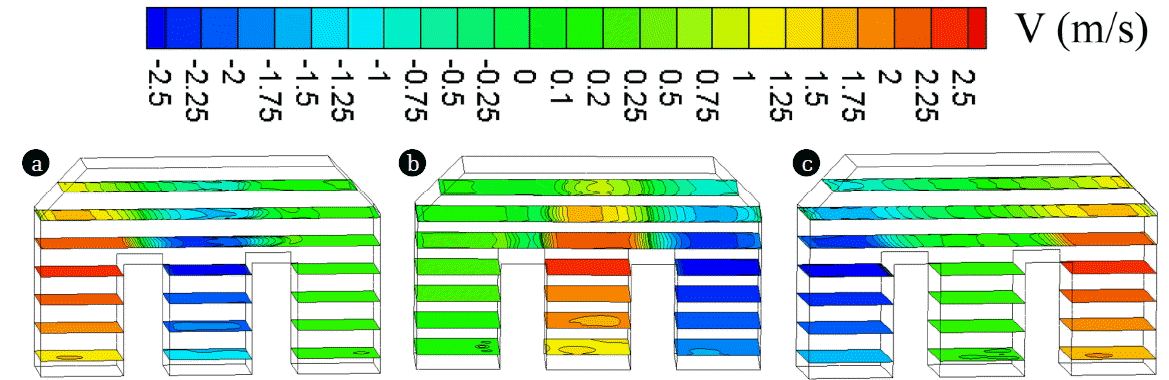
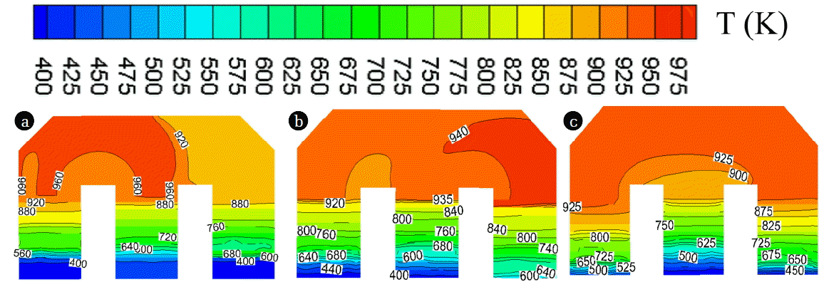
Fig. 5 and Fig. 6 show the RTO internal temperature distributions over one cycle. Though the regenerators could effectively heat methanol and absorb heat from hot flue gas, the temperature of the packed beds differed between cycles. The regenerators allowed both the temperature and velocity to rapidly reach homogeneous states. Temperature changes were small at constant heights in the packed beds, and remained slightly higher in the center and slightly lower in the periphery. Since the initial OCT was not high and the reaction of methanol was sufficient, the temperature gradient inside the oxidation chamber was small. Due to methanol combustion, the highest temperatures occurred in the space between the methanol entry and exit planes in the oxidation chamber. In the role of regenerator cut angle, there was no obvious low-temperature oxidation zone. In the third cycle, methanol entered the oxidation chamber from the rightmost packed bed and flowed into the leftmost packed bed. The methanol had its longest residence time during this cycle, and the oxidation chamber reached its highest temperature range. From an engineering perspective, increasing the burning time of the exhaust gas improved the treatment of VOCs.
3.3. RTO Internal Temperature Distribution
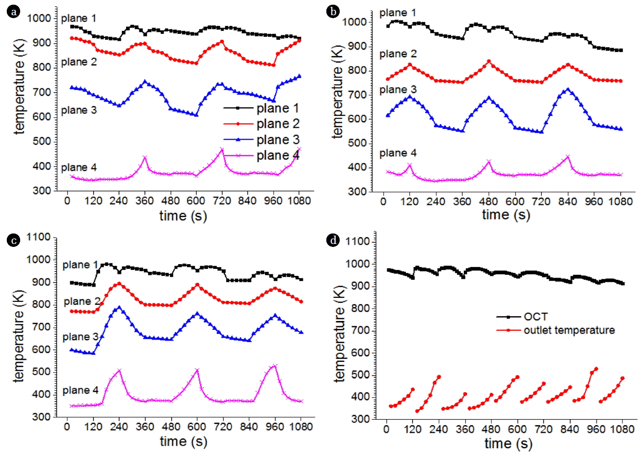
Fig. 7 shows the average temperature (in the same plane as the measuring point) of each plane of the packed beds over three cycles, as well as the changes over time in the average oxidation chamber and RTO outlet temperatures. As indicated in this figure, the uppermost plane of the packed beds is close to the oxidation chamber, allowing the high temperature flue gas in the chamber to influence its temperature changes. This plane had a subtle periodicity similar to that of the oxidation chamber. The two intermediate horizontal planes, located in the central part of the packed beds, experienced lower temperatures during intake (when heat was transferred to the exhaust gas) and higher temperatures during exhaust (when the regenerators absorbed heat from the flue gas). Temperatures decreased and increased to equal extents; in many cycles, their fluctuation ranges were essential equivalent, and the periodic nature of their variation was obvious. The periodicity of the bottom plane was not obvious, but its peak temperature appeared periodically.
The outlet temperature experienced variations due to the three different packed beds outlets for each period, and increased during each valve switching time. Affected by the air volume, valve switching time, exhaust gas concentration, and packed beds temperature, the amplitude of outlet temperature variations was different each cycle.
3.4. RTO Thermal Efficiency and VOCs Removal Rate
Thermal efficiency can be defined as:
(2)
where Tc represents the OCT, To represents the outlet temperature, and Tin represents the inlet temperature.
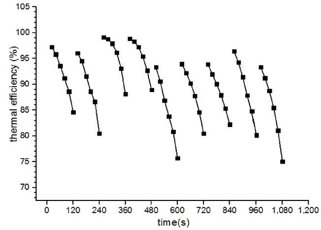
Thermal efficiency can be used to evaluate the heat transfer performance of RTOs. Greater thermal efficiencies correspond with higher energy utilization and, associatively, an improved heat exchange effect. As shown in Fig. 8, the thermal efficiency of the RTO studied in this paper was always > 75% and the average thermal efficiency over multiple cycles was calculated to be 90%. As the outlet temperature was not continuous, the thermal efficiency was also discontinuous. The thermal efficiency decreased with time in each cycle, but its amplitude differed every cycle.
Removal rate is the destruction rate of VOCs after treatment. The lower the concentration of methanol at the gas outlet was, the higher the VOCs removal rate would be The concentration of methanol at the RTO gas outlet was very low in all cases, with an average removal rate as high as 98%. This agrees with the experimentally calculated removal rate. As such, waste gas removal was not further analyzed.
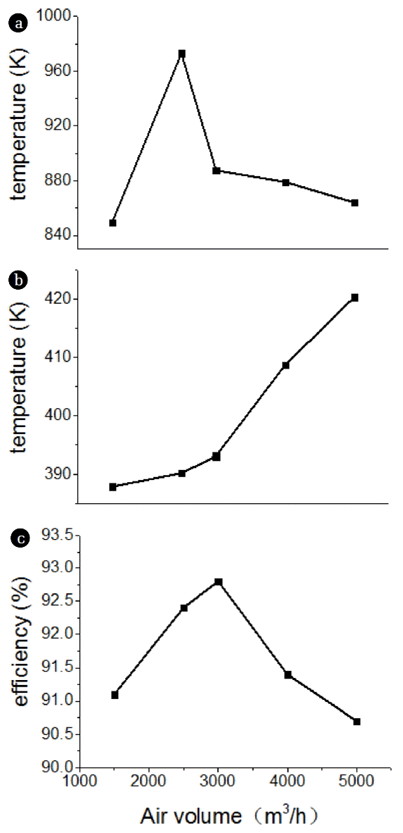
3.5. Effect of Air Volume on RTO
Fig. 9 shows the effect of air volume on the RTO. It can be seen that the RTO already has the best air volume: when the air volume was less than this optimized value, the OCT increased with increases in volume, and when the air volume was greater, the OCT decreased with increases in volume. For simulated velocities between 0.514–1.715 m/s, The best chamber velocity was 1.03 m/s, corresponding to a volume of 3,000 m3/h. Smaller air volumes consume auxiliary fuel to maintain the set OCT, reducing economic benefits. Greater air volumes reduce the gas residence time, allowing part of the gas to be blown out without reacting and reducing VOCs removal rates. Larger air volumes also absorbed more heat during gas intake, creating greater heat losses during the exothermic process. As a result, the outlet temperature rose and thermal efficiency decreased.
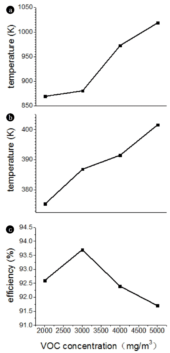
3.6. Effect of VOCs Concentration on RTO
Fig. 10 shows the effect of VOCs concentrations on the RTO, demonstrating that both the oxidation chamber and outlet temperatures increased with increasing concentrations: as the exhaust gas concentration increased, the amount of gas involved in the chemical reaction increased, raising both the amount of heat released and the OCT. VOCs were oxidized in the oxidation chamber before entering the packed beds, where they radiated heat. The regenerators absorbed this heat, and its temperature rose. When the regenerators became saturated, heat was removed by the gas and the outlet gas temperature increased, reducing thermal efficiency. Overall, the RTO average thermal efficiency remained > 90% at various concentrations. For this RTO, the optimum concentration was 3,000 mg/m3, at which the RTO had a higher OCT and a lower exit temperature, creating the highest thermal efficiency and best economy benefits. These simulation results demonstrated that an exhaust gas concentration of 2,000 mg/m3 is sufficient for a self-running RTO to prevent extra fuel consumption using an air volume of 2,500 m3/h and valve switching time of 120 s.
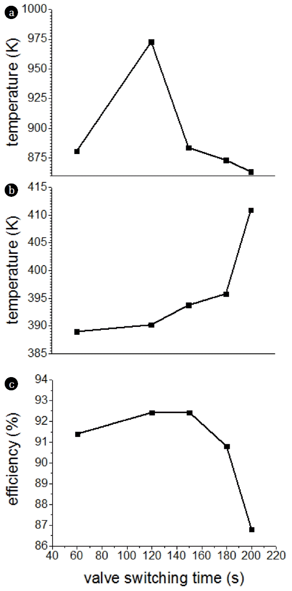
3.7. Effect of Valve Switching Time on RTO
The valve switching time influenced heat distribution in the packed beds and temperature in the oxidation chamber, as shown in Fig. 11. When the valve switching time was too short, valves experienced more wear; however, when the switching time was too long, the amount of gas flowing through the packed beds each period increased. Excess gas flow caused gas to absorb heat from the regenerators on the intake side, significantly reducing the regenerators temperature and simultaneously lowering the temperature of gas entering the oxidizer chamber, increasing the heat the oxidizer chamber must absorb to reach the ignition point. On the exhaust side, regenerators heat absorption had a certain limit, after which the outlet gas temperature increased and RTO thermal efficiency decreased. The simulation results demonstrated that a switching time of 120 s created the highest thermal efficiency, thus raising the OCT and lowering the outlet temperature. The optimal switching time of this RTO is thus 120 s.
From the above sections, it can be stated that the RTO studied in this paper works best under the following conditions: a velocity of 1.03 m/s, VOCs concentration of 3,000 mg/m3, and switching time of 120 s. Typically, the initial designs of RTOs with predetermined air volumes are based on an optimal velocity, and VOCs concentrations are then used to determine the packed beds height. The proposed simulation can then be used to determine the valve switching time, identifying the optimal operating parameters for application in industrial production.
4. Conclusions
This study simulated an RTO applied to VOCs treatment and obtained the following results:
The transient simulation results generated in this study were compared to data collected in industrial experiments. The temperature error of most measurement points was within 5%, demonstrating the assumptions and simulation methods used in this paper were correct and can be used to accurately reflect the operation characteristics of an RTO.
Velocity and temperature field analyses for this RTO revealed that the honeycomb regenerator has a flow-equalizing effect which is beneficial to the uniform distributions of velocity and temperature.
Air volume, VOCs concentration, and valve switching time significantly influence the OCT, RTO outlet temperature, and RTO thermal efficiency. These characteristics also demonstrate periodicity.
The proposed simulation determined the average temperature of the oxidation chamber can be kept stable after the VOCs concentration reaches a specific value. With sufficient residence time in the oxidation chamber and a strong turbulent flow, the RTO can reach a VOCs removal rate > 98% and average thermal efficiency of 90% at a lower oxidation chamber temperature.
References
1. Kim SW, Mckeen SA, Frost GJ, et al. Evaluations of NOx and highly reactive VOC emission inventories in Texas and their implications for ozone plume simulations during the Texas Air Quality Study 2006. Atmos Chem Phys. 2011;11:11361–11386.
2. Kirkeskov L, Witterseh T, Funch LW, et al. Health evaluation of volatile organic compound (VOC) emission from exotic wood products. Indoor Air. 2009;19:45–57.
3. Gong QC, Niu ZG, Chen YX, Zhang Y. Research advances review on the health-hazard assessment of volatile organic compounds in ambient atmosphere. J Saf Environ. 2012;12:84–88.
4. Yang XZ. Treatment technology for volatile organic waste gas. Environ Sci Manage. 2016;96–100.
5. Buss W, Mašek O. High-VOC biochar – Effectiveness of post-treatment measures and potential health risks related to handling and storage. Environ Sci Pollut Res. 2016;23:1–10.
6. Dumont E, Darracq G, Couvert A, et al. VOC absorption in a countercurrent packed-bed column using water/silicone oil mixtures: Influence of silicone oil volume fraction. Chem Eng J. 2011;168:241–248.
7. Kemp J, Zytner RG, Bell J, Parker W, Thompson D, Rittmann BE. A method for determining VOC biotransformation rates. Water Res. 2000;34:3531–3542.
8. Pei P, Wang Q, Wu D. Application and research on Regenerative High Temperature Air Combustion technology on low-rank coal pyrolysis. Appl Energ. 2015;156:762–766.
9. Liu R, Liu Y. Application and impact analysis of honeycomb regenerator in the regenerative heating furnace. Ind Furnace. 2016;38:7–9.
10. Zhong L, Liu Q, Wang W. Computer simulation of heat transfer in regenerative chambers of self-preheating hot blast stoves. ISIJ Int. 2007;44:795–800.
11. Xiao Q. Improvement and application of regenerative thermal oxidizer. Chinese J Environ Eng. 2011;5:1347–1350.
12. Nakayama K, Fujita S, Iijima S, Nishimura I, Shimota H, Katagiri T. Combustion and decomposition of VOCs from shell moulds by regenerative thermal oxidizer. Int J Cast Metal Res. 2013;21:265–268.
13. Ma X, Lin J, Branch TE. Analysis on feasibility of treating coated organic waste gas with regenerative thermal oxidizer. Environ Sci Manage. 2016;41:125–128.
14. Iijima S, Nakayama K, Kuchar D, Kubota M, Matsuda H. Optimum conditions for effective decomposition of toluene as VOC gas by pilot-scale regenerative thermal oxidizer. World Acad Sci Eng Technol. 2011;44:492–497.
15. Cheng WH, Chou MS, Lee WS, Huang BJ. Applications of low-temperature regenerative thermal oxidizers to treat volatile organic compounds. J Environ Eng. 2002;128:313–319.
16. Chou MS, Hei CM, Huang YW. Regenerative thermal oxidation of airborne N, N-dimethylformamide and its associated nitrogen oxides formation characteristics. J Air Waste Manage. 2007;57:991–999.
17. Choi BS, Yi J. Simulation and optimization on the regenerative thermal oxidation of volatile organic compounds. Chem Eng J. 2000;76:103–114.
18. Xiao Q, Jiang ZY, Zhang XX. Numerical simulation and application of a regenerative thermal oxidizer. J Univ Sci Technol Beijing. 2011;33:632–635.
Fig. 1
Schematic of the RTO.
Fig. 2
Comparison of experimental and simulated values. a) packed bed 1, b) packed bed 2, c) packed bed 3, d) oxidation chamber.
Fig. 3
Y-axis of vertical section velocity distributions. a) Period 1, b) Period 2, c) Period 3.
Fig. 4
Y-axis of horizontal section velocity distributions. a) Period 1, b) Period 2, c) Period 3.
Fig. 5
Vertical section temperature distributions. a) Period 1, b) Period 2, c) Period 3.
Fig. 6
Horizontal section temperature distributions. a) Period 1, b) Period 2, c) Period 3.
Fig. 7
RTO internal temperature changes over time. a) packed bed 1, b) packed bed 2, c) packed bed 3, d) oxidation chamber and outlet.
Fig. 8
Thermal efficiency changes over time.
Fig. 9
Influence of air volume on RTO. a) oxidation chamber, b) outlet, c) thermal efficiency.
Fig. 10
Effect of VOC concentration on RTO. a) oxidation chamber, b) outlet, c) thermal efficiency.
Fig. 11
Effect of valve switching time on RTO. a) oxidation chamber, b) outlet, c) thermal efficiency.
Table 1
Primary Physical Properties of the Regenerators
Density kg/m3
Cp J/(kg·K)
Thermal conductivity W/(m·K)
Porosity %
2,000
1,000
1.8
65
Table 2
RTO Operating Status
Cycle no.
Period no.
Regenerative chamber 1
Regenerative chamber 2
Regenerative chamber 3
1
in
out
purge
I
2
purge
in
out
3
out
purge
in
II, III…
Table 3
Simulation Study Case List
Case no.
VOC inlet velocity (m/s)
VOC concentration (mg/m3)
Switching time (s)
1
0.514
4,000
120
2
0.857
4,000
120
3
1.028
4,000
120
4
1.371
4,000
120
5
1.715
4,000
120
6
0.857
2,000
120
7
0.857
3,000
120
8
0.857
5,000
120
9
0.857
4,000
60
10
0.857
4,000
240
11
0.857
4,000
500
Table 4
Comparison between the Simulation and Experimental Data